External and internal rotor motors describe which part turns. That distinction changes the mechanical layout of a fan, but it does not by itself determine efficiency, life, temperature rating, or the right duty point. For an OEM enclosure, start with the space available for the complete fan, the required airflow against system resistance, and the conditions around the motor. Then compare exact assemblies rather than treating rotor position as a performance grade.
Identify the moving part before comparing the fan
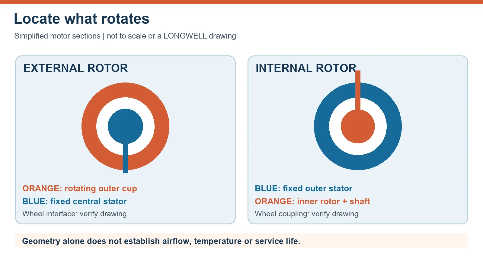
In an external rotor arrangement, the stator is near the centre and the rotor turns around it as an outer cup. In an internal rotor arrangement, the rotor turns inside the stator and drives an output shaft. That is the structural difference. It says nothing by itself about the fan wheel’s final diameter, blade geometry, airflow, bearing life, or control method.
The schematic below isolates that difference. It is a teaching diagram, not a cross-section of a particular LONGWELL model. A complete fan drawing must show how the impeller is fixed, where the stationary support sits, how bearings are carried, and what clearance the surrounding equipment must provide.
What a named LONGWELL motor actually shows
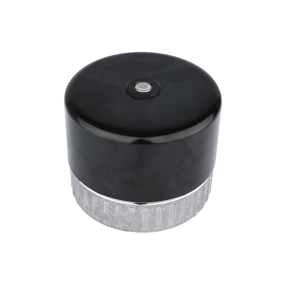
LONGWELL’s reviewed product records include the LW-DCM092H-01 external rotor motor. The photograph below shows its visible cylindrical cup and lower mounting form. The company catalogue separately lists external rotor AC, DC and EC motor families. The photo identifies one exterior configuration; it cannot reveal the internal winding layout, prove a fan curve, or establish that this model fits the reader’s application.
For a wider starting set, the LONGWELL external rotor motor family shows available product routes. Treat the family as a shortlist, not as evidence that every item shares a mounting pattern, protection rating, or motor control interface. Request the exact suffix and revision before using a catalogue dimension in a CAD assembly.
Compare the complete installed envelope
A direct wheel-to-rotor layout can reduce the need for an extended output shaft in some compact fans. It does not mean that every external rotor fan is shorter than every internal rotor fan. The wheel diameter, hub, inlet, guards, cable exit, electronics and service clearance may dominate the installed depth. Draw a box around the whole assembly, then compare candidate drawings on the same mounting plane.
An internal rotor assembly may put a shaft between the motor and wheel; it can also place the motor outside a particular air path if the fan design allows it. That is an arrangement choice, not a universal high-temperature entitlement. Both routes need the exact motor and fan ratings for the air temperature, dust, moisture and operating mode. Compare the cable and controller location as carefully as the mechanical envelope.
Do not convert motor geometry into a performance claim
Earlier versions of this guide made categorical claims about a power crossover, lower running temperature, easier balancing and comparable bearing life. Those outcomes require model-specific measurements and assembly details. The reviewed LONGWELL catalogue contains individual motor specifications, but it does not provide a controlled, matched external-versus-internal rotor fan test supporting a universal ranking. Rotor position alone cannot supply one.
For airflow selection, ask for the fan assembly curve at the intended speed and density, and calculate the resistance of the duct, filters, heat exchanger, grille or enclosure. A maximum airflow value and maximum pressure value are different endpoints. LONGWELL’s fan-curve guide explains why the useful operating point is where the fan and system curves meet. If noise or energy matters, compare those measurements at the same duty, not only at catalogue free-air conditions.
Check thermal and control boundaries
Where the motor and electronics sit determines what surrounding air and radiant heat they encounter. A wheel moving air past a motor does not establish a safe winding or electronics temperature at low speed, after a blocked inlet, or in a hot enclosure. Ask for the exact permissible ambient and motor temperature, cooling conditions, duty cycle, protection behaviour and control range of the proposed assembly. The answer may differ between AC, DC and EC variants within the same geometry.
The maintenance route also belongs to the exact design. Some integrated assemblies are serviced as a unit; other motors have replaceable components or a different service policy. Do not assume that external means disposable or internal means rewindable. Request the spare-part strategy and access envelope together with the installation drawing.
A selection brief that leads to a usable comparison
Send both candidates the same operating brief: required flow at estimated system resistance, electrical supply, speed or control signal, operating modes, air temperature and contaminants, orientation, mounting plane, maximum assembly envelope, acoustic target and service access. Add the expected filter or system changes over time. Ask for a drawing and fan curve for each named model and revision, plus any relevant test conditions.
The result is a comparison of two complete fan solutions, not a vote on the word “external” or “internal”. If one route offers a better mechanical fit, verify that it still meets the operating point and thermal boundary. If the duty is safety critical, the responsible engineer should review the full system and applicable standard before release.
Need a motor-and-fan shortlist for a defined enclosure? Send the duty point, assembly space and operating conditions to sales@longwellfans.com.
Choose the right external rotor motor
Longwell manufactures 11 external rotor motors in-house. Send airflow, static pressure and voltage — an engineer replies with a matching model, performance curve and price within one working day.