
Fans for Automation and Machine-Control Cabinet Cooling
Automation cabinets contain controllers, drives and power supplies whose heat losses change with machine operation. Prepare a cooling brief from those losses and the enclosure air path. Select the fan together with the filter arrangement, available space and controller’s response to a loss of airflow.
Design cooling for production, idle and service conditions
The same automation cabinet may experience sustained production, short load peaks and long idle periods. Each can create a different thermal condition. This page helps machine builders define the fan duties and interfaces that need checking before a sample is installed, without assuming that a fan determines motion-control performance.
How a Filter Changes Control-Cabinet Cooling
A cabinet fan’s free-air rating describes a different condition from working behind a filter. The installed path includes filter media, electronics and an outlet. Dust loading changes resistance, while an edge leak creates an unfiltered route.
Follow the air through the process
Use a complete inlet-to-outlet route
The illustrated intake fan is low on one side of the control enclosure. After crossing the filter, air enters the electronics space and leaves through an upper opening on the opposite side.
Pass air through the medium
Porous media allows air to pass while intercepting some airborne particles. The enlarged openings and gold dust are a qualitative explanation; they do not specify a filter class or measured efficiency.
Account for loading resistance
Accumulated dust constricts the medium. At a fixed fan speed, increased resistance can reduce airflow. A free-air fan rating therefore does not establish the flow available in the cabinet.
Prevent unfiltered edge leakage
A gap between the medium and its seal can feed air into the fan inlet without crossing the medium. This is an inlet-filtration bypass, separate from air that bypasses an internal heat sink.
Restore the installed passage
The serviceable filter, correctly seated seal and clear outlet work together. Confirm the condition of the whole passage and that ambient air is suitable for direct ventilation.
Airflow function
- Create the pressure difference needed to pass air through the installed filter.
- Provide useful cabinet ventilation after allowing for all flow restrictions.
- Support the intended intake-to-exhaust direction.
What can change the result
- Dust loading reduces usable airflow at the same fan speed.
- A displaced filter seal allows unfiltered intake air.
- A blocked upper outlet restricts the same cabinet passage.
Start with the complete air path
Share your layout and the information you already have. Unknown values can be identified before a configuration is selected.
Match the fan to this air path
A cabinet fan must deliver useful airflow against the filter and enclosure resistance. Review LONGWELL compact DC axial options using both clean and loaded filter conditions, together with the seal around the filter.
Where it sits
Move filtered intake air through cabinet electronics toward the opposing outlet.
Why consider this configuration
A cabinet fan must deliver useful airflow against the filter and enclosure resistance. Review LONGWELL compact DC axial options using both clean and loaded filter conditions, together with the seal around the filter.
Check the result in your equipment
Application questions
Why is the installed airflow lower than the free-air rating?
The filter, cabinet and outlet oppose the flow. The fan must operate where its pressure capability meets the complete system’s resistance.
Does a spinning fan prove the filter is clear?
No. The rotor can continue turning with a loaded filter. Fan status and the condition of the airflow passage are different observations.
Can a filter-edge leak improve cooling?
It may provide an easier path for air, but that air bypasses the medium. It does not preserve the intended filtration performance.
Is direct ventilation appropriate for every machine enclosure?
No. Ambient temperature, oil mist, moisture and other contaminants can require a different enclosure-cooling method.
Review cabinet airflow
Send the cabinet layout or existing fan model. Add the heat load, ambient conditions, filter pressure drop and available supply voltage when known.
A layout, installation photos or your existing model is enough to start the discussion.
Map heat across the machine cycle
List heat-producing cabinet components and their losses during production, startup, idle and any cleaning or shutdown state. Identify temperature-sensitive controls and concentrated heat sources. Prepare the cooling requirement from that operating sequence so the fan evaluation covers sustained conditions as well as short load changes.
- Production and idle heat-loss schedule
- Temperature-sensitive component locations
- Startup and shutdown operating conditions
Check filters and restricted cabinet space
Provide the cabinet layout with ducts, cable routes, filters and louvres. Review resistance at the planned filter replacement condition and check for recirculation around partitions. Confirm that the fan inlet, wiring and service area remain accessible after the cabinet is fully populated with production equipment.
- Clean and service-limit filter resistance
- Cable routes, partitions and recirculation
- Inlet clearance and installed service access
Agree monitoring and the trial test
Define the speed command and feedback needed by the machine controller. Specify the response to a stopped fan, restricted intake or lost signal. During the trial, record cabinet temperatures and fan operation over the representative machine cycle, keeping the configuration and measurement locations with the results.
- Speed command and feedback signal
- Cooling-fault logic and restart sequence
- Trial conditions and temperature measurement points
Match the fan family to the equipment.
Compare the proposed model at the required airflow and pressure, then check the installation and control interface.
Panel-mounted centrifugal options
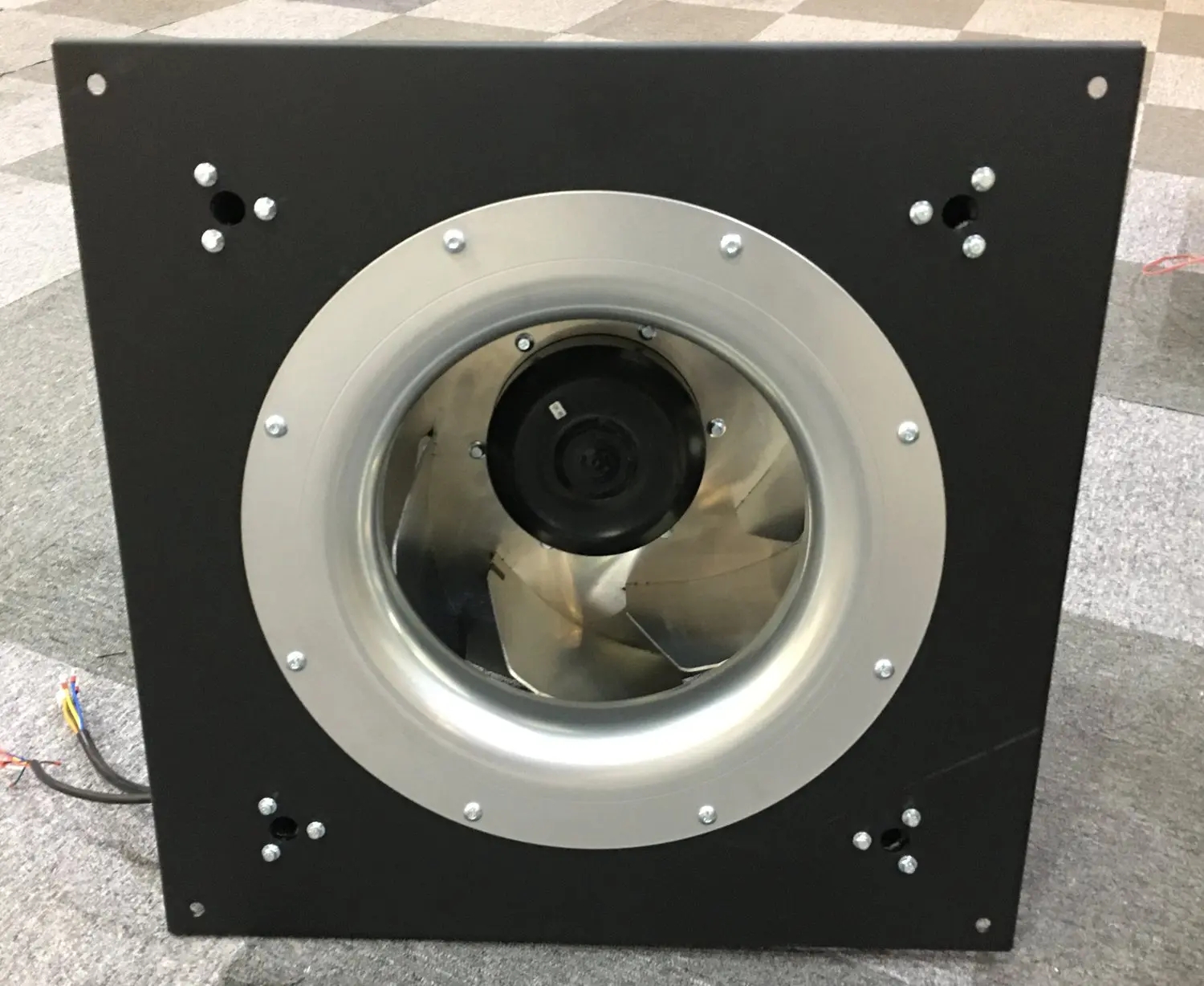
Review centrifugal configurations for populated control cabinets with filters or internal channels. Match pressure, panel dimensions and inlet clearance before selecting the motor and controls.
Explore this fan family →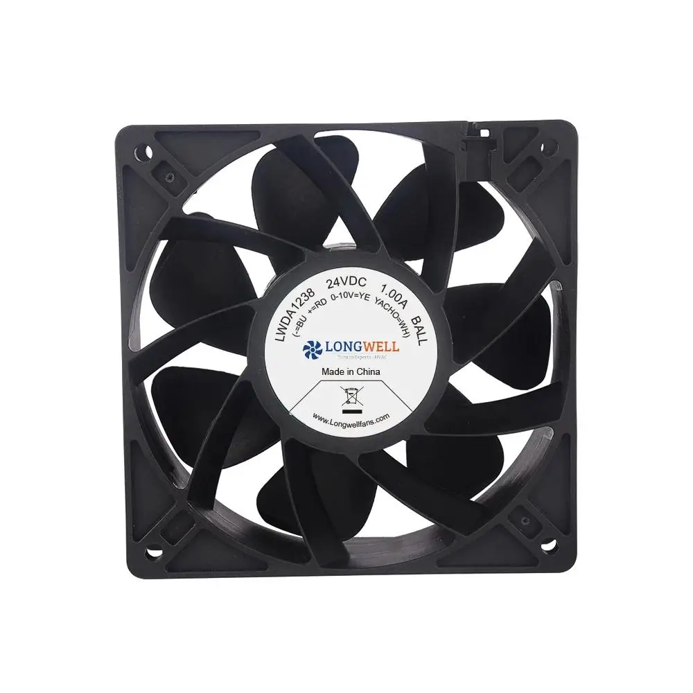
Compact DC axial fans
Review compact DC axial formats for individual controllers or small enclosures. Confirm installed airflow, cable retention and feedback requirements under the intended machine operating cycle.
Explore this fan family →Product images show family configurations. Request the drawing, curve and electrical information for the exact model being considered.
What should your fan enquiry include?
Share these application details so the fan proposal can be reviewed against your equipment.
Bring the equipment context to the fan review.
A drawing, the operating condition and a clear control requirement make the proposed configuration easier to compare. For a replacement, include the existing nameplate and wiring details.
Discuss your application →Reference material for the next step.
Compare compact formats and request connection details and operating data for the controller or enclosure position being reviewed.
Engineering checklistFan replacement and controls checklist ↗Use the checklist to freeze the mounting, electrical supply and monitoring interface before ordering replacement or trial fans.
Catalogs support initial selection. Confirm the current specification and approved configuration with the project team.
What should be measured during a cabinet trial?
Record temperatures at the relevant components and air-path locations, together with the fan operating state, ambient conditions and machine load. Include representative sustained and idle periods. Keep the installed filter, cabinet layout and control configuration with the record so the result can be interpreted.
Is a higher free-air fan rating always helpful?
The cabinet resistance and inlet arrangement determine the installed operating point. A larger free-air rating may not address restricted channels or recirculation, and can affect power or sound. Review the system path first, then compare candidate curves and the complete cabinet’s thermal result.
Continue with the equipment you are designing.
Share your equipment and operating conditions.
Send the drawing, target duty and project timing. Add the existing fan details when you need a replacement.