
Fan arrays for air-handling and cooling units
Design the fan array around the airflow the unit must deliver, the resistance it must overcome and the space available for each module. Define normal duty, reduced-speed operation and selected fault cases before comparing fan count, installed power or the practical route for maintenance.

Specify the complete parallel-fan arrangement
Multiple fans operate within a common air-handling system, so the selection depends on shared pressure, plenum geometry and control behaviour. Start with a drawing and a duty schedule. Use these to compare a proposed array with the existing fan section or a new unit design.
Find the operating point of each module
Provide the total airflow and system pressure for the required modes. Establish how the proposed fans share that airflow in the common plenum, considering inlet conditions and speed commands. Review the available fan curves at the resulting points; the nameplate maximum of each module is not the installed array duty.
- Total system airflow and pressure
- Fan count, speed and shared plenum
- Clean and loaded filter conditions
Check service and stopped-fan behaviour
Show the fan spacing, maintenance opening and removal direction. A stopped module can create a reverse-flow path, depending on the arrangement. Review isolation and any backflow-control components with their added resistance, and confirm how a technician can service the module without blocking the operating fans.
- Module spacing and access route
- Electrical isolation and replacement path
- Reverse-flow control and added resistance
Make redundancy and savings measurable
Describe the faults the system must tolerate and the remaining duty required for each. Include power and controller faults where the project requires them. For a retrofit comparison, record the baseline and proposed input power at equivalent delivered duty, then apply the actual operating schedule rather than a generic saving percentage.
- Agreed fault scenarios and capacity
- Power, alarms and controller sequence
- Same-duty baseline and operating hours
WATCH THE APPLICATION PRINCIPLE · ENGLISH
Why an air handler uses a fan wall
Parallel plug fans feed one plenum while facing a common pressure difference. If an idle branch remains open, air can flow backward through it. Isolation and coordinated controls determine how the remaining modules operate.
English narration and on-screen captions · 77 seconds · Equipment and flow paths are schematic.
Product scope in this film: LONGWELL backward-curved EC plug-fan candidates must be reviewed as a complete array. The film does not establish N+1 capacity, full airflow recovery after a fault or a measured energy saving.
Explore the LONGWELL fan family · Share your equipment and air-path requirements
Match the fan family to the equipment.
Compare the proposed model at the required airflow and pressure, then check the installation and control interface.
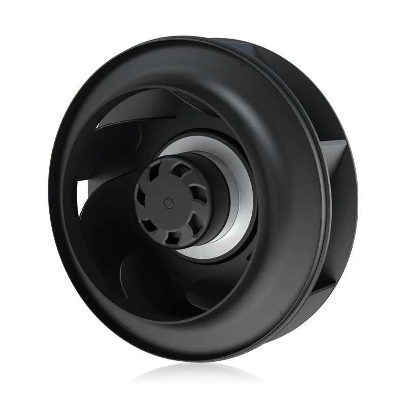
Backward-curved centrifugal fans
Review backward-curved configurations as individual array modules. Assess inlet clearance, mounting and the pressure-flow point assigned to each fan in the common system.
Explore this fan family →
RLM plug-fan assemblies
Review framed plug-fan assemblies when their installation envelope suits the fan section. Include the support structure and replacement route in the array layout.
Explore this fan family →Product images show family configurations. Request the drawing, curve and electrical information for the exact model being considered.
What should your fan enquiry include?
Share these application details so the fan proposal can be reviewed against your equipment.
Reference material for the next step.
Use the series information to narrow the mechanical format; confirm inlet conditions, controls and the proposed model performance separately.
Series catalog · PDFRLM series plug fans ↗Review assembly formats and series dimensions, then request the current curve and approved drawing for the complete offered model.
Engineering checklistFan replacement: fit and controls ↗Check operating duty, mounting, supply, wiring and control behaviour before treating an existing fan and a proposed replacement as interchangeable.
Catalogs support initial selection. Confirm the current specification and approved configuration with the project team.
Can I add the free-air ratings of all the fans?
That sum describes neither the common system pressure nor the installed airflow. Establish the array operating point using the fan curves and the shared air path, then consider inlet effects and control settings. Confirm delivered flow in the assembled unit.
What makes a redundancy claim reviewable?
State the specific failure and the minimum remaining duty, then document how the array, power supplies and controls respond. Include reverse-flow behaviour and any isolation devices. The claim should follow the equipment test and acceptance criteria for that exact arrangement.
Continue with the equipment you are designing.
Share your equipment and operating conditions.
Send the drawing, target duty and project timing. Add the existing fan details when you need a replacement.