
Fan selection for server and electronics airflow
Establish whether the enquiry concerns a server chassis, an electronics enclosure or the room-cooling equipment around it. Each has a different airflow path and control boundary. Provide component temperature limits, resistance, installation space and electrical interfaces before comparing a fan format or evaluating a replacement.
Separate chassis cooling from enclosure and room airflow
Heat sinks, internal obstructions and inlet restrictions influence chassis duty, while a cabinet or room has a different air path. Use this page to prepare a component-level enquiry. The product references support a format discussion; suitability depends on the proposed equipment and complete fan specification.
Why Separate CPU and Memory Air Paths in a Server?
Inside a server, component placement changes the cooling job. If air passes through one hot component before reaching another, the second receives air that is already warmer. This is a thermal interaction between loads.
Follow the air through the process
Compare series and parallel paths
In the series example, CPU-heated air continues toward the memory. A parallel layout splits the incoming air so the processor and memory can receive separate supplies, reducing that upstream preheating.
A shroud preserves the split
The air shroud and its seals keep each branch pointed at its intended components. If air escapes over the top or around a heat sink, fan airflow can bypass the hardware that needs cooling.
Each branch has its own resistance
Air must pass between real heat-sink fins and memory modules, not through their solid surfaces. The split depends on each branch's resistance. A free-air fan rating does not tell you the installed flow through both paths.
Verify the actual configuration
Not every server uses this layout. Component population, inlet temperature and controls change the requirement. Measure the component temperatures and delivered flow in the intended chassis configuration, with its cover and shroud installed.
Airflow function
- At the chassis fan bank, feeding separated CPU and memory branches maintained by the internal shroud.
- Compact DC axial families can be compared at the installed operating point and required envelope. Both branches need useful flow through their components rather than an easier route around them.
What can change the result
- Serial placement preheats a downstream cooling load.
- A missing shroud allows air to bypass components.
- Unequal branch resistance leaves one load with insufficient flow.
Start with the complete air path
Share your layout and the information you already have. Unknown values can be identified before a configuration is selected.
Match the fan to this air path
Evaluate LONGWELL compact DC axial fan families from the required operating point, envelope and control interface. Confirm the complete server module and electrical compatibility rather than assuming a catalog fan is a drop-in replacement.
Where it sits
At the chassis fan bank, feeding separated CPU and memory branches maintained by the internal shroud.
Why consider this configuration
Compact DC axial families can be compared at the installed operating point and required envelope. Both branches need useful flow through their components rather than an easier route around them.
Check the result in your equipment
Discuss your server airflow branches
Send CPU and memory heat loads, component arrangement, pressure and flow in each branch, maximum inlet temperature, fan envelope and supply, control and complete-module compatibility. Ask LONGWELL to review a suitable configuration, fan curve, drawing and control details. A layout or existing fan model can start the review.
A layout, installation photos or your existing model is enough to start the discussion.
Engineering references
Map the component-to-air cooling requirement
Identify the components to be cooled, their allowable temperatures and the maximum specified inlet condition. Supply the chassis or enclosure drawing, including heat sinks, filters and cable obstructions. Establish the required airflow at that resistance with the equipment designer and define how temperatures will be measured during validation.
- Heat load and component temperature limits
- Chassis restrictions and cable layout
- Required duty at maximum inlet temperature
Check the actual electrical interface
Record the complete existing part number and connector pinout for a replacement. Confirm supply, speed command, feedback and alarm behaviour with the controller requirements. Include starting and low-speed operation in the review; matching diameter or connector shape does not establish compatibility with firmware or the equipment’s protection sequence.
- Voltage, connector and pin assignment
- Command and tachometer or alarm behaviour
- Start-up and minimum operating-speed response
Define blocked-path and fan-fault tests
Specify the operating states that the equipment must tolerate, including reduced airflow or a stopped fan where required. Review the remaining air path and the controller response before agreeing a model. Complete the assessment in the actual chassis or enclosure, with the relevant component temperatures and input conditions recorded.
- Normal and defined abnormal air paths
- Fault detection and equipment response
- Temperature measurement locations and acceptance
Match the fan family to the equipment.
Compare the proposed model at the required airflow and pressure, then check the installation and control interface.
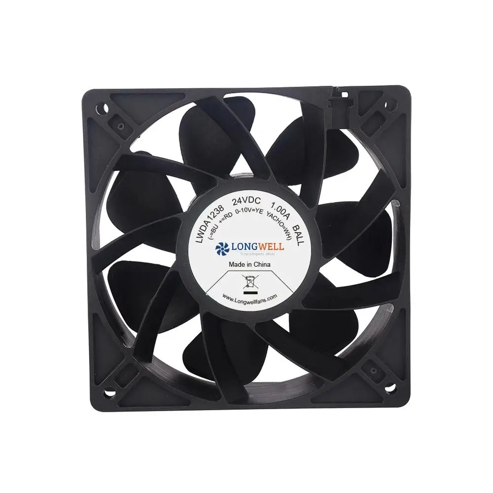
Compact DC axial fans
Review compact square-frame DC fans for chassis and electronics positions with matching dimensions. Confirm pressure-flow duty, supply, connector pinout and controller feedback for the exact version.
Explore this fan family →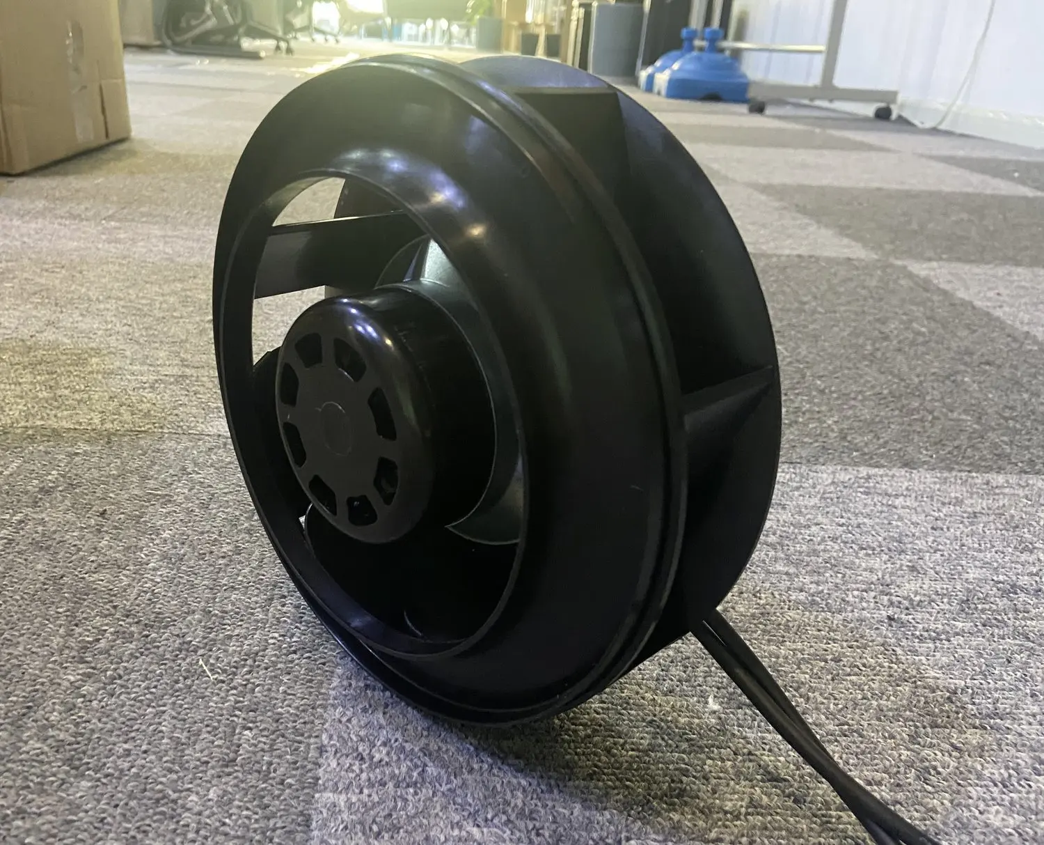
Cabinet-level centrifugal configurations
Review compact centrifugal formats for a cabinet or auxiliary enclosure with a matching radial air path. Confirm installed duty and dimensions separately from server-chassis fan requirements.
Explore this fan family →Product images show family configurations. Request the drawing, curve and electrical information for the exact model being considered.
What should your fan enquiry include?
Share these application details so the fan proposal can be reviewed against your equipment.
Bring the equipment context to the fan review.
A drawing, the operating condition and a clear control requirement make the proposed configuration easier to compare. For a replacement, include the existing nameplate and wiring details.
Discuss your application →Reference material for the next step.
Compare compact fan formats, then request the selected electrical specification, connector definition and operating data for the enclosure.
Series catalog · PDFEC backward-curved centrifugal fans ↗Use the series information to narrow the mechanical format; confirm inlet conditions, controls and the proposed model performance separately.
Engineering checklistFan replacement: fit and controls ↗Check operating duty, mounting, supply, wiring and control behaviour before treating an existing fan and a proposed replacement as interchangeable.
Catalogs support initial selection. Confirm the current specification and approved configuration with the project team.
Can a cabinet fan be treated as a server-chassis replacement?
No. The mounting format, pressure-flow duty, supply and control interface can be very different. Identify the cooling boundary first and compare the complete part specification. Any proposed chassis replacement needs validation with the actual server equipment and its controller.
Does matching the connector confirm compatibility?
Verify the pin assignment, voltage, signal reference, command range and feedback behaviour, as well as the mechanical connector. Check start-up and fault handling in the equipment. A physically matching connector can still carry a different electrical or control interface.
Continue with the equipment you are designing.
Share your equipment and operating conditions.
Send the drawing, target duty and project timing. Add the existing fan details when you need a replacement.