
Fan and Motor–Impeller Selection for FFU Equipment
Specify the airflow, filter resistance, installation space and control requirements together. LONGWELL can review your FFU fan or motor–impeller requirement against a defined configuration and drawing revision.
See the housing and motor together
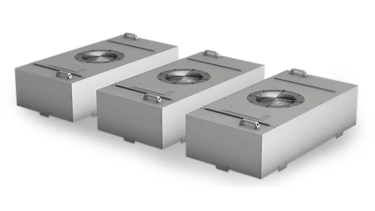
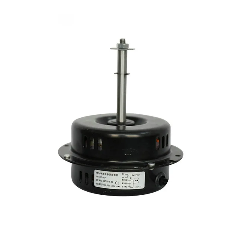
Start with the operating conditions
For a useful selection review, provide the required airflow and the resistance the fan must overcome in the assembled unit. Identify the filter condition used for each pressure value. Maximum free-air flow and maximum static pressure are different endpoints; neither describes the complete operating requirement.
| Selection input | What to provide |
|---|---|
| Airflow | Required airflow, units, operating modes and acceptable variation. |
| Filter and system resistance | Filter identification, clean and design-loaded resistance, and other pressure losses in the unit. State the airflow associated with each pressure value. |
| Installation | Housing dimensions, inlet arrangement, impeller envelope, mounting points and service access. |
| Power | Supply voltage, frequency and available electrical connection. |
| Control and feedback | Controller details, required speed commands, feedback, fault indication and behavior if the control signal is lost. |
| Acceptance conditions | Applicable temperature, airflow-distribution, power, noise and vibration requirements, with the proposed test method. |
Check mechanical fit before confirming a replacement
A matching impeller diameter is only one part of the comparison. Review the inlet, motor support, mounting pattern, overall depth, rotation, cable exit and access for servicing against the actual FFU housing. Where a reference unit is being replaced, provide its nameplate, drawing, wiring information and installation photographs.
Use a clearly identified drawing revision for the selection and sample review. Record any changes to the inlet, impeller, support or cable assembly so the tested configuration can be reproduced.
Confirm the control configuration
Specify whether the equipment requires fixed speeds, multiple speed settings or a variable speed command. Ask for the wiring and interface definition for the exact proposed model. Supply voltage, a speed-control input and a feedback output have different functions and must be checked separately.
If your system requires 0–10 V, PWM, a speed feedback signal or a communication protocol, include the controller specification in the review. Compatibility, pin assignments, signal limits and fault behavior must be confirmed for the selected configuration.
Plan validation in the assembled FFU
Agree on the filter conditions and operating points to be evaluated. Record airflow, pressure, input power and speed together for each condition. If constant-airflow operation is required, define the acceptable airflow range and verify the available speed and power margin as resistance increases.
Measure airflow distribution, noise and vibration in the agreed housing and mounting arrangement. State the measurement positions and conditions with the results. Module-level findings should be reported within their tested scope; qualification of the complete cleanroom remains a separate system task.
Review the test method and source documents
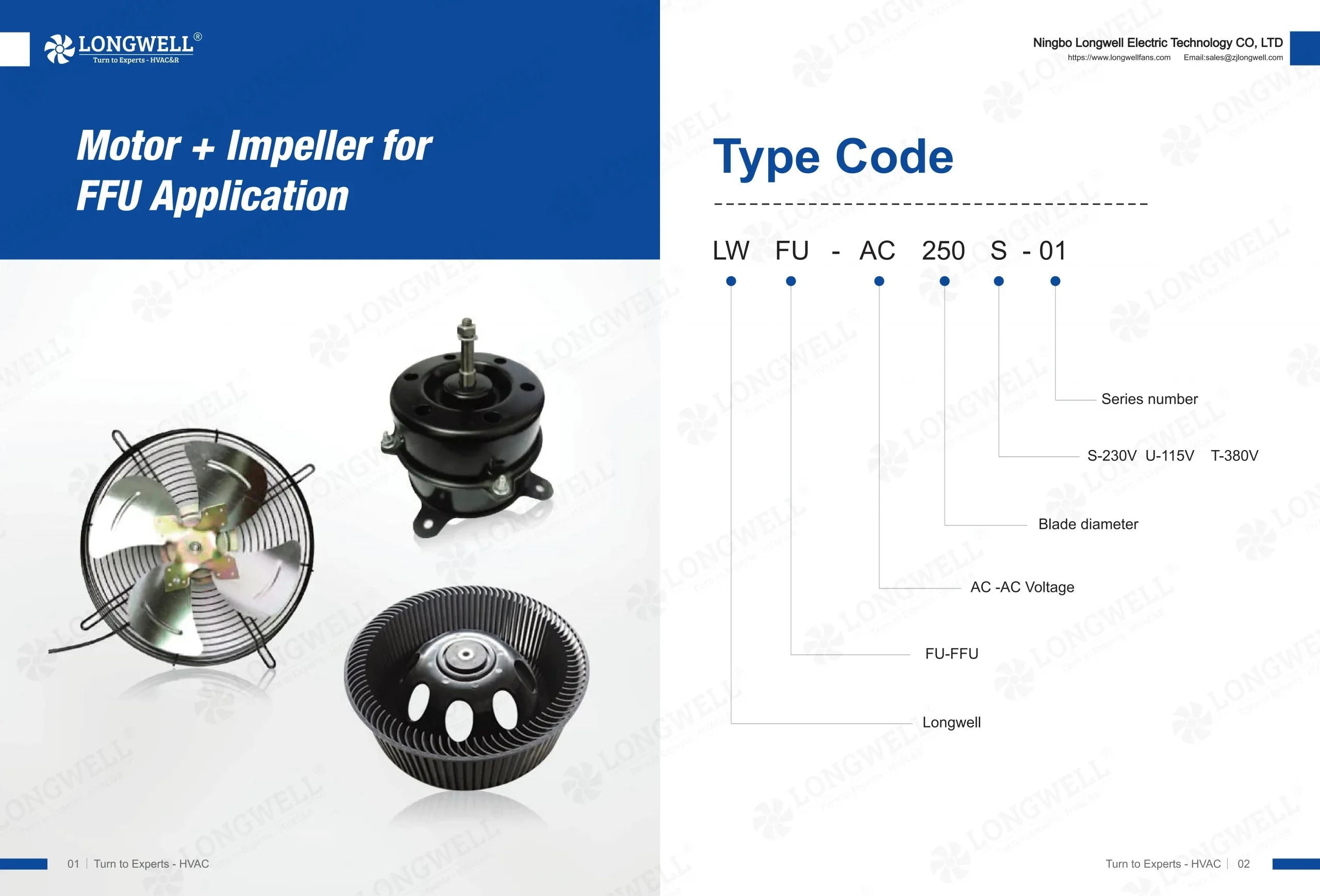
FFU Motor + Impeller catalog
Browse the published series, outline drawings and catalog data. Use this as a starting reference, then request the approved specification for the exact model and configuration.
View FFU catalog (PDF)Request a configuration-specific documentation package
Ask for the proposed full model code, revision-controlled drawing, operating data, wiring definition and available supporting test or compliance documents. The selection review should identify the configuration covered, the evidence available and any checks still needed on your equipment.