
Fans for Fuel-Cell Enclosure and Electronics Cooling
Start a fuel-cell fan enquiry by identifying the exact air circuit. LONGWELL axial and centrifugal references shown here support enclosure ventilation and electronics-cooling review. Stack process-air and gas-circuit proposals need a separate definition of medium, pressure, materials and equipment validation before any model can be assessed.
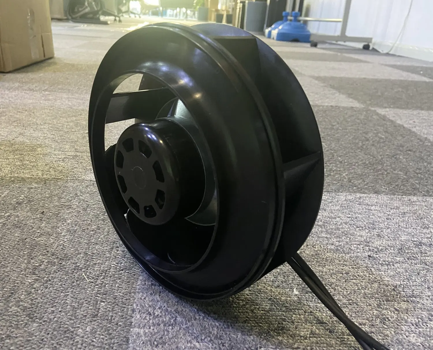
Keep cabinet cooling separate from process circuits
A fuel-cell package can contain electronics, auxiliaries and process components with different airflow requirements. Define the cooling circuit served by each fan and record the surrounding conditions. The product references below are for a documented enclosure or electronics-airflow enquiry, with any process or gas duty reviewed separately.
Why a Fuel Cell Needs Controlled Cathode Air
A fuel cell needs oxygen for its chemical reaction, as well as a way to remove heat and manage water. This PEM example follows a separate ambient-air blower feeding the cathode, while hydrogen stays in its own anode circuit. Air delivery must follow the stack load and the resistance of the complete air path.
Follow the air through the process
Two gases stay on different sides
Hydrogen enters the anode side; air supplies oxygen to the cathode. Protons cross the membrane, while electrons travel through the external electrical circuit. The two supply gas streams do not share a pipe.
Follow one cathode channel
The blower drives air along narrow cathode flow channels. At the reaction layer, oxygen combines with protons and returning electrons to form water. Heat is produced as well.
Air demand follows electrical load
When the stack delivers more current, it consumes more oxygen. The controller adjusts blower output to the required air supply. Actual flow and pressure matter; motor speed alone cannot prove delivery.
Keep the channels usable
Cathode air also carries water toward the outlet. Water management must preserve membrane hydration while avoiding blocked gas passages. A flooded channel leaves less useful space for oxygen transport.
Airflow function
- Supply oxygen-bearing ambient air to cathode channels.
- Overcome the actual air-path resistance over the stack load range.
- Support controlled transport of reactants and cathode outlet water.
What can change the result
- Insufficient oxygen delivery when load rises.
- Water blocks a portion of the cathode channels.
- A blower chosen by maximum free-air flow misses the installed pressure requirement.
Start with the complete air path
Share your layout and the information you already have. Unknown values can be identified before a configuration is selected.
Match the fan to this air path
Cathode air supplies a reactant as well as helping transport outlet water. LONGWELL lists the LWBD36 family for fuel-cell applications; evaluate it using the stack air requirement across the load range.
Where it sits
Supply controlled ambient air to the fuel-cell cathode through the specified air circuit.
Why consider this configuration
Cathode air supplies a reactant as well as helping transport outlet water. LONGWELL lists the LWBD36 family for fuel-cell applications; evaluate it using the stack air requirement across the load range.
Check the result in your equipment
Application questions
Is this blower circulating hydrogen?
No. This example is the ambient-air cathode circuit. Hydrogen supply and any anode recirculation require their own specified components.
Can maximum vacuum select a cathode blower?
No. A vacuum endpoint does not establish positive-pressure flow at the intended stack operating point. Request the correct delivered-air curve.
Can a cooling fan replace the cathode blower?
The functions differ. Cooling moves heat; this blower must deliver the required reaction air through the actual cathode resistance.
Discuss cathode air supply
Start with the cathode air schematic or existing blower model. Add the stack flow-pressure curve, inlet conditions, control range and water-management requirements when available.
A layout, installation photos or your existing model is enough to start the discussion.
Map heat sources in the enclosure
Identify power electronics and auxiliary components that depend on forced cooling. Provide heat-load estimates, permitted component temperatures and an enclosure drawing showing inlet and discharge locations. Describe filters, internal obstructions and recirculation risks so the fan duty can be evaluated against the actual cooling path rather than the cabinet volume alone.
- Component heat loads and temperature limits
- Inlet, outlet and obstruction layout
- Filters and internal recirculation paths
Define operating and monitoring requirements
Record the required cooling airflow and pressure at each relevant equipment load. Specify supply, command and feedback interfaces together with the enclosure controller’s response to a fan fault. Include ambient temperature, humidity and service access so the selected assembly can be assessed for the intended cabinet and maintenance arrangement.
- Cooling duty across equipment loads
- Supply, command and fan feedback
- Ambient exposure and service access
Separate process-air and gas requests
If a fan proposal concerns stack process air or another gas circuit, provide that circuit’s medium and operating envelope independently of enclosure cooling. Identify material, leakage and contamination requirements and the equipment-level validation plan. A cabinet-fan photograph or family catalogue does not establish the suitability of a process-circuit assembly.
- Process medium and pressure range
- Materials, leakage and contamination requirements
- Equipment validation and required documents
Match the fan family to the equipment.
Compare the proposed model at the required airflow and pressure, then check the installation and control interface.
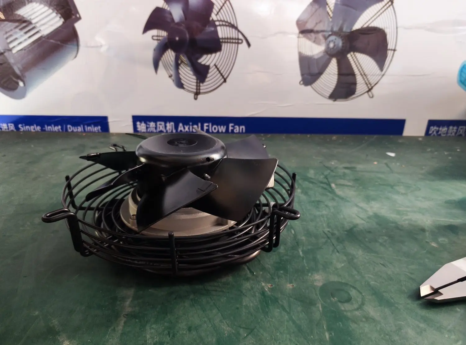
EC axial fans
Review axial formats for a defined enclosure cooling path where the airflow and resistance suit the layout. Specify ambient conditions and the required monitoring interface.
Explore this fan family →EC backward-curved centrifugal fans
Consider centrifugal formats for electronics airflow through a documented enclosure or filter path. Compare the full assembly at the specified cooling duty and installation clearances.
Explore this fan family →Product images show family configurations. Request the drawing, curve and electrical information for the exact model being considered.
What should your fan enquiry include?
Share these application details so the fan proposal can be reviewed against your equipment.
Bring the equipment context to the fan review.
A drawing, the operating condition and a clear control requirement make the proposed configuration easier to compare. For a replacement, include the existing nameplate and wiring details.
Discuss your application →Reference material for the next step.
Review axial fan formats and series information before requesting operating-point, acoustic and installation data for the selected configuration.
EC centrifugal series · PDFEC backward-curved fan catalogue ↗Use the family references for initial comparison, then confirm the selected assembly with its inlet geometry and required operating point.
Engineering checklistFan replacement controls checklist ↗Record electrical, control and mechanical interfaces when comparing an existing fan with a proposed replacement in the complete equipment.
Catalogs support initial selection. Confirm the current specification and approved configuration with the project team.
Do the illustrated cooling fans establish hydrogen-circuit suitability?
These references support enclosure and electronics-cooling enquiries. A hydrogen or other gas-circuit proposal requires its own medium, material, leakage, electrical and equipment-validation requirements. Suitability must be assessed for the complete proposed model and circuit; it cannot be inferred from these cooling-fan images or family names.
What should be supplied for a fuel-cell electronics cabinet?
Provide the component heat loads and temperature limits, the cabinet airflow drawing and the resistance of filters or internal passages. Add ambient conditions, supply and control signals, and the required fault response. This creates a defined cabinet-cooling duty that can be reviewed independently of stack process circuits.
Continue with the equipment you are designing.
Share your equipment and operating conditions.
Send the drawing, target duty and project timing. Add the existing fan details when you need a replacement.