
Axial fans for heat exchangers and condensers
Select the fan around the coil’s air-side requirement and the space surrounding it. Heat-exchanger duty depends on airflow through the fins, the inlet conditions and the equipment configuration. Bring coil pressure loss, mounting geometry, discharge clearance and the control schedule into the fan review from the start.
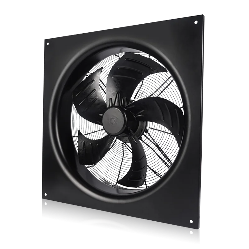
Match fan placement to the coil face
This page focuses on integrating fans with air-cooled heat exchangers and condensers. Review whether the fan pushes or draws air through the coil, how the inlet ring or shroud is arranged and where warm discharge air travels. Treat the fan and coil layout as a combined design.
Use the coil designer’s air-side requirement
Provide the airflow needed at the intended heat-rejection condition and the corresponding coil pressure loss. Include guards, grilles and any additional air-path resistance. Review the selected fan at these conditions and at the planned reduced-speed modes, keeping fan electrical input separate from the complete refrigeration system performance.
- Coil airflow and pressure-loss data
- Design inlet-air temperature
- Additional guards and grille resistance
Review distribution and discharge recirculation
Show the fan position relative to the coil, including the inlet ring, shroud and mounting panel. Identify walls, screens and neighbouring units that could obstruct discharge or return warmed air to the inlet. Check the actual installation clearances rather than relying on an unobstructed product photograph.
- Blow-through or draw-through layout
- Shroud, inlet ring and fan spacing
- Walls, screens and adjacent-unit clearance
Set the operating range and site conditions
Describe the supply, speed command and controller requirements across the intended season. Include outdoor temperatures, moisture and any corrosion or cleaning exposure. State the sound assessment location and operating speed, then request the relevant model data to compare candidates within the limits of the proposed equipment installation.
- Supply and required speed range
- Weather and cleaning exposure
- Sound limit with operating conditions
Match the fan family to the equipment.
Compare the proposed model at the required airflow and pressure, then check the installation and control interface.
EC axial fan configurations
Review EC axial configurations for airflow across heat-exchanger fins. Confirm coil resistance, mounting-ring geometry and the complete model’s operating range before final selection.
Explore this fan family →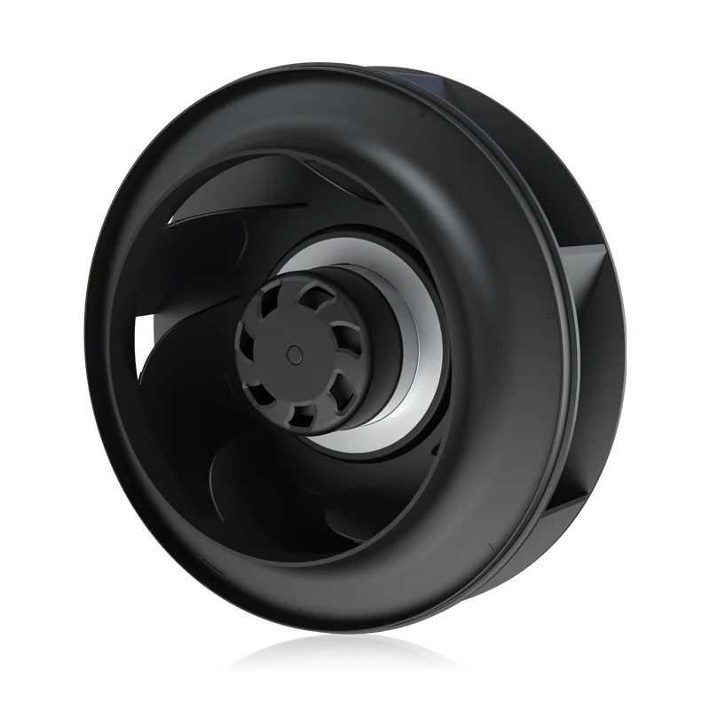
Backward-curved centrifugal fans
Review centrifugal configurations for enclosed heat-exchanger equipment with a radial discharge or added air-path resistance. Establish the required housing and inlet conditions with the equipment designer.
Explore this fan family →Product images show family configurations. Request the drawing, curve and electrical information for the exact model being considered.
What should your fan enquiry include?
Share these application details so the fan proposal can be reviewed against your equipment.
Bring the equipment context to the fan review.
A drawing, the operating condition and a clear control requirement make the proposed configuration easier to compare. For a replacement, include the existing nameplate and wiring details.
Discuss your application →Reference material for the next step.
Compare the axial series and installation dimensions before requesting operating-point, electrical and environmental data for the selected configuration.
Series catalog · PDFEC backward-curved centrifugal fans ↗Use the series information to narrow the mechanical format; confirm inlet conditions, controls and the proposed model performance separately.
Engineering checklistFan replacement: fit and controls ↗Check operating duty, mounting, supply, wiring and control behaviour before treating an existing fan and a proposed replacement as interchangeable.
Catalogs support initial selection. Confirm the current specification and approved configuration with the project team.
Should the fan always be placed behind the coil?
Choose the blow-through or draw-through arrangement with the heat-exchanger designer. Available space, distribution, fan temperature and inlet geometry influence the result. Review the proposed assembly and its performance conditions rather than assuming one position suits every coil or enclosure.
Will a higher free-air rating improve heat rejection?
Not necessarily. The useful comparison is delivered airflow against the coil and installation resistance. Coil distribution, ambient conditions and discharge recirculation also matter. Ask for the fan operating point and evaluate heat rejection using the complete equipment configuration.
Continue with the equipment you are designing.
Share your equipment and operating conditions.
Send the drawing, target duty and project timing. Add the existing fan details when you need a replacement.