
LONGWELL · Air conditioning
Air-conditioning fans,
selected for your equipment.
From AHUs and fan coil units to cleanroom modules and heat pumps, find the right starting point for your airflow, installation and control requirements.

Start with your equipment
What are you designing?
The application sets the questions. Compare fan options at the required duty point, inside the actual installation.
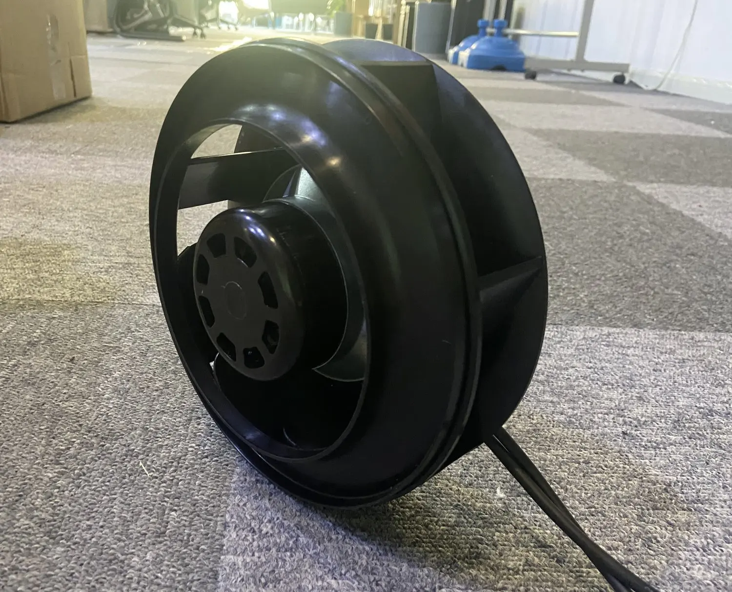
AHU & ventilation units
Move air through coils, filters and ductwork. Start with the required airflow at the installed system resistance.
Duty point · Fan chamber · Control signal
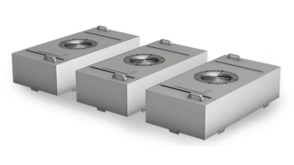
FFU & cleanroom modules
Select the fan, motor-impeller assembly and housing together. Include both clean-filter and final filter resistance.
Filter resistance · Module depth · Speed control
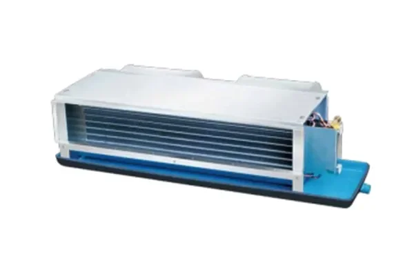
Fan coil units
Match the fan arrangement to the coil, cabinet and available duct pressure, then check sound at the occupied-room operating speed.
External static pressure · Cabinet fit · Room acoustics
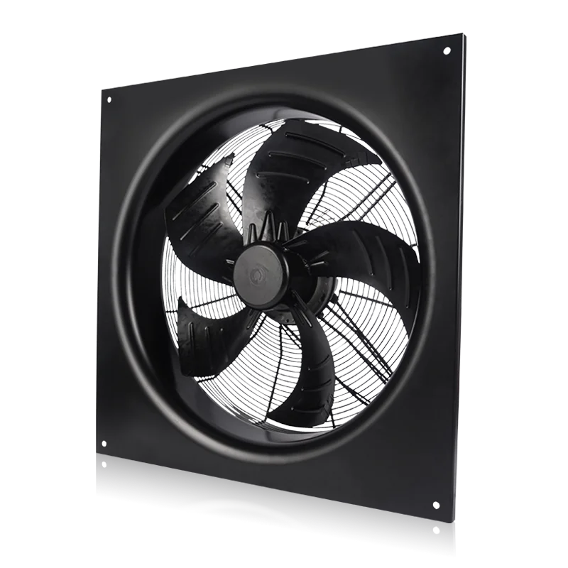
Heat pump outdoor units
Review coil resistance and the fan inlet, guard and discharge together. Specify the operating conditions and defrost sequence.
Coil resistance · Weather exposure · Part-load sound
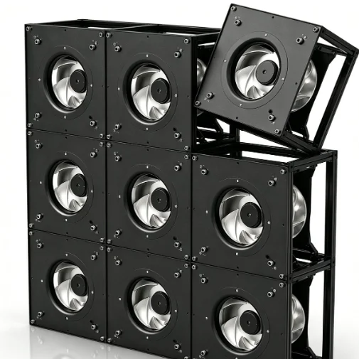
Precision cooling & fan arrays
Plan airflow across the cabinet and check the fan-array duty under the required availability scenario.
Air distribution · Array layout · Service access
Heat exchangers & condensers
Choose airflow from the equipment heat-rejection requirement. Check coil pressure loss and recirculation in the final layout.
Coil duty · Inlet clearance · Speed range
From requirement to sample
A useful selection starts
with the complete system.
Airflow alone does not define a fan. Share the pressure requirement, available space and control interface, then confirm the proposed assembly in your equipment.
Define airflow & pressure
Include filters, coils, ductwork and the expected operating range.
Check the physical fit
Provide the drawing, inlet clearance, mounting and service space.
Specify the interface
Confirm the supply, speed command and feedback needed by the controller.
Agree sample acceptance
Review airflow, input power, sound and controls in the intended assembly.
Useful technical resources
Bring drawings to the conversation.
Use the series catalogs to narrow the options. Request a current model drawing, curve and wiring diagram before approval.
Series dimensions and product options for an initial selection review.
Open RLM catalog ↗Motor and fan family references for FFU and EFU equipment.
Open FFU catalog ↗Fan coil unit configurations and reference product information.
Open fan coil catalog ↗Product families for coil airflow and heat-rejection applications.
Open axial catalog · 37 MB ↗Catalogs are series references. Dimensions, interfaces and ratings depend on the selected model and document revision.
Explore the complete range of applications
More ways to find your solution.
Tell us what the fan
needs to do.
Send the application, target airflow and pressure, available dimensions, supply and control requirements. For a replacement, include the nameplate and existing drawing.