
Fans and assemblies for room fan-coil units
Match the fan-coil unit to the room terminal: installation depth, coil and filter resistance, required airflow and the control sequence. For concealed or ducted equipment, include the connected air path and service access. Review the fan, coil, drain tray and controller as a specified combination.
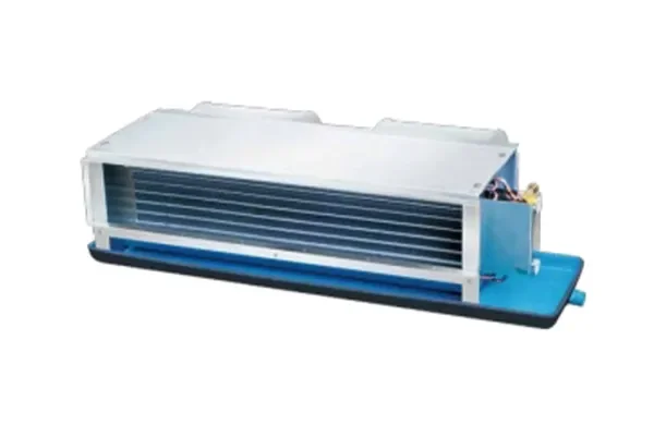
Choose the terminal format before the fan setting
A fan-coil circulates room air across a heating or cooling coil. Its installation may be concealed, exposed or connected to short ductwork. This page helps compare the mechanical format and fan interface while keeping coil duty, condensate management and room control in the equipment review.
How a Hydronic Fan Coil Moves Room Heat into Water
A hydronic fan coil brings cooling into a room using moving water and moving air. In this unit, there is no local refrigerant compressor.
Follow the air through the process
The blower moves room air over the coil
Return air passes the filter and enters the blower. The blower sends it through the finned coil and back to the room. The air-side pressure duty includes the installed filter, coil and outlets.
Water takes heat out of that air
Chilled water arrives from the building system and flows inside the coil tubes. Room heat crosses the fins and tube walls into the water, which returns warmer.
Condensate has its own path
When the coil surface is below the air’s dew point, moisture can condense on it. The drain pan collects this water and directs it to a drain. Condensate is separate from the chilled-water circuit.
Control the water and the air
A room controller can regulate the water valve and blower speed according to the system design. Less room load does not require the same air and water flow as peak cooling.
Airflow function
- Between the return-air filter and hydronic coil, moving room air through the terminal and back to the occupied space.
- LONGWELL fan-coil blower assemblies are a relevant configuration for the terminal air path. The paired centrifugal arrangement must fit the coil, outlets and enclosure while meeting the controller requirement.
What can change the result
- A loaded filter or restricted outlet changes the air delivery even if water conditions are unchanged.
Start with the complete air path
Share your layout and the information you already have. Unknown values can be identified before a configuration is selected.
Match the fan to this air path
LONGWELL supplies fan-coil blower assemblies and hydronic units. For an EC blower, share the required airflow, installed resistance, mounting space and control interface. Confirm the coil’s cooling duty at the specified water and air conditions.
Where it sits
Between the return-air filter and hydronic coil, moving room air through the terminal and back to the occupied space.
Why consider this configuration
LONGWELL fan-coil blower assemblies are a relevant configuration for the terminal air path. The paired centrifugal arrangement must fit the coil, outlets and enclosure while meeting the controller requirement.
Check the result in your equipment
Discuss your fan coil terminal
Send airflow at coil and outlet resistance, chilled-water conditions and room load, mounting, sound and controller interface. Ask LONGWELL to review a suitable configuration, fan curve, drawing and control details. A layout or existing fan model can start the review.
A layout, installation photos or your existing model is enough to start the discussion.
Engineering references
Allow for coil, filter and duct resistance
State the room airflow required at each intended speed. Include the coil, return filter, grille and any connected ductwork in the pressure budget. Identify whether the filter data describes a clean or loaded condition, and coordinate the airflow schedule with the unit’s heating or cooling design.
- Room airflow at intended speed steps
- Coil, filter and external resistance
- Supply and return grille arrangement
Fit the unit and retain service access
Provide the ceiling void or terminal enclosure dimensions, mounting points and removable panels. Check access to the fan, filter and drain tray rather than only the external unit size. Include the proposed orientation and pipe or cable routes so the final arrangement can be maintained after installation.
- Height, depth and fixing pattern
- Filter and fan removal route
- Drain-tray access and installation orientation
Review low-speed sound and room controls
Agree the room sound target with its measuring position and operating setting. Confirm the available supply, speed steps or command signal and any required feedback. Review minimum operating speed, starting behaviour and the interaction with valves and thermostats using the actual proposed fan-coil configuration.
- Sound target and measurement setting
- Supply and speed-control interface
- Start-up, low speed and valve sequence
Match the fan family to the equipment.
Compare the proposed model at the required airflow and pressure, then check the installation and control interface.
Fan-coil units and components
Review complete fan-coil formats when coil, drainage and room controls are part of the requirement. Confirm the offered unit configuration and its installation dimensions.
Explore this fan family →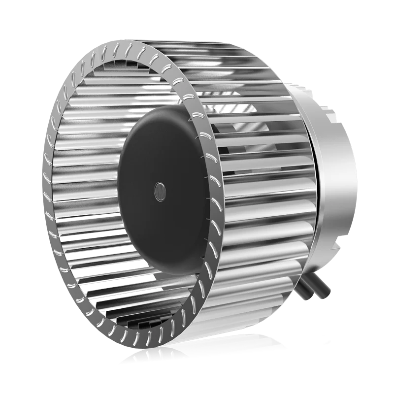
Forward-curved impellers and fans
Review forward-curved fan components for terminal designs with a matching housing and motor arrangement. Select the assembled fan against coil and filter resistance.
Explore this fan family →Product images show family configurations. Request the drawing, curve and electrical information for the exact model being considered.
What should your fan enquiry include?
Share these application details so the fan proposal can be reviewed against your equipment.
Bring the equipment context to the fan review.
A drawing, the operating condition and a clear control requirement make the proposed configuration easier to compare. For a replacement, include the existing nameplate and wiring details.
Discuss your application →Reference material for the next step.
Review unit and component formats; confirm the proposed coil, fan, drainage and controller combination against the room-terminal requirement.
Engineering checklistFan replacement: fit and controls ↗Check operating duty, mounting, supply, wiring and control behaviour before treating an existing fan and a proposed replacement as interchangeable.
Catalogs support initial selection. Confirm the current specification and approved configuration with the project team.
Does the fan establish room dehumidification performance?
Dehumidification depends on coil conditions, airflow, drainage and the unit control sequence. A fan specification alone does not establish it. Provide the proposed cooling conditions and room requirements, then assess the complete fan-coil configuration using the equipment supplier’s applicable data.
Can I choose the quietest setting from the catalog alone?
Check how the published sound was measured, the fan speed and the unit configuration. Ducts, grilles, mounting and room conditions can change the result. Agree the intended operating setting and assessment location before comparing candidates for the installed room terminal.
Continue with the equipment you are designing.
Share your equipment and operating conditions.
Send the drawing, target duty and project timing. Add the existing fan details when you need a replacement.