
Heating
Where the Heat Goes
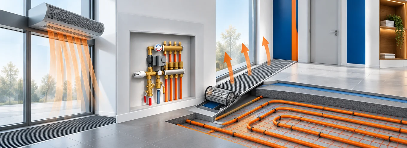
From the trench convector cavity to the over-door terminal to the AHU heating coil: cross-flow fans from Ø30 to Ø65 mm in coupled 200–1,080 mm barrels, forward-curved centrifugal for fan coils, backward-curved EC for AHU and RTU duty — with the 24 V SELV supplies, 0–10 V thermostat tracking and 18 dBA quiet operation that heating terminals are actually specified on.
Why LONGWELL for Heating Equipment
Heating terminals are bought on numbers the end user never sees: how shallow the cavity can be, how quietly the fan tracks a room thermostat, and how many barrel lengths × control variants one supplier can hold without the BOM exploding. The platform is built around those.
Ø30–65 mm, Extended by Coupling
Trench cavities leave almost no vertical space — impellers go down to Ø30 mm. Barrel length is not a tooling problem: one, two or three impellers coupled on a single shaft cover 200–1,080 mm in steps, from one fixed set of diameters.
Safety Extra-Low Voltage, Thermostat-Tracking
Underfloor and in-floor installations specify safety extra-low voltage: 24 V DC brushless with a 0–10 V input so the terminal follows the room thermostat continuously instead of switching between fixed speeds. 12 V variants for vehicle-mounted and portable units.
AC Legacy and DC Smart on the Same Mechanics
The same manufacturer usually keeps a non-smart line on 230 V 50 Hz AC while the new line goes DC. One supplier carries both drive families against the identical mechanical envelope — and knows exactly where AC ends: shaded-pole torque runs out at roughly 620 mm of barrel.
18–20 dBA Is a Sales Argument
In heating terminals the fan is audible in a quiet living room at night. Aluminium impellers with protective grill, balanced rotors and sealed ball or oil bearings hold 18 dBA on the largest coupled floor assemblies and ≤20 dBA on wall convectors — a figure the terminal OEM can print.
Dozens of SKUs Without the Chaos
A single terminal order can carry dozens of barrel lengths × control variants × left/right motor positions, with a firm lead time written into the proforma before payment. The selection system — fixed diameters, coupling scheme, two drive families, two control boards — is what keeps that manageable.
What's Inside This Pack
Six sections, written the way a heating-equipment engineer buys: cavity and duty first, part numbers second, honest boundaries third.
- §16 Heating Airflow Segments
Underfloor, trench & floor convectors, wall convectors, fan coils, air curtains, AHU/RTU - §2Product × Application Matrix
3 platforms, 10 duty rows, model numbers included - §3Segment Deep Dives
Challenges + recommended configurations - §4Market & Trend Radar
Hydronic heating & air curtain market data, low-temperature emitter shift - §5Certifications & T1 Test Library
What we hold, what we do per project, what is not in scope - §6Reference Cases
Hydronic terminal programme (216 threads) · air curtain OEM programme (31 threads)
6 Heating Airflow Segments, One Platform Logic
Each segment differs in cavity height, static pressure, voltage and noise ceiling — but they share the same cross-flow first logic and the same control layer, which is what makes a single-supplier BOM practical across a heating product portfolio.
Underfloor Heating Systems
Fan-assisted floor terminals and underfloor circulation units inside the lowest layer of the building: safety extra-low voltage, dust and moisture protection, and noise the occupant cannot hear at night.
Trench & Floor Convectors
The star segment: Ø30–65 mm impellers coupled to 200–1,080 mm barrels inside perimeter trench cavities and free-standing floor convectors. A long-running supply programme built on exactly this geometry.
Wall Convectors & Fan-Assisted Radiators
Wall-mounted heating terminals and radiator boosters on legacy 230 V AC, with a DC upgrade path for the smart line — same envelope, one supplier.
Fan Coils & Heating Terminals
Hydronic fan coils (heating and cooling duty) and fan-assisted heating terminals: forward-curved centrifugal on EC or AC drives, sized for low static and quiet room-side operation.
Air Curtains & Over-Door Heating
Even discharge across the full door width from long cross-flow barrels in matched LH/RH pairs — plus the EC axial or centrifugal upgrade path as premium models move to variable speed.
AHU, RTU & Ducted Heat Distribution
Heating coils inside air handling units and rooftop units, plus EC duct fans for warm-air distribution. The heat-source side — heat pump and condenser fans — is covered on the dedicated heat-pump page.
3 Platforms × Heating Duty
Three released platforms cover the whole page. The cross-flow family is the star; the centrifugal and axial families carry the distribution and upgrade duty.
- DC platform: 12 / 24 V brushless, 2,000–2,400 rpm, 0–10 V stepless (LW375 / LW500 boards)
- AC platform: 230 V 50 Hz, fixed / tapped speed — for legacy terminal lines
- Noise: 26–42 dB released range · 18 dBA on largest coupled floor assemblies · ≤20 dBA LWCA-60
- Released models: LWCD-30290MG-04 (30 mm, 26–34 dB) · LWCD-40420MN-07 (40 mm, 33–37 dB) · LWCD-50150MN-07 (50 mm, 37–42 dB)
- Poland floor programme: LWCD-45630MN-03, -45750MN-02, -45950MN-01, -65435MN-01, -65620MN-02, -65880MN-01, -81440MN-01, -81620MN-01, -81860MN-01 — 30–50k pcs/yr
- High-duty variant: LWCD-45350NG-01 — 238 m³/h at 9.6 W (24 V DC, 0.4 A, 2,000 rpm)
- FCU fan coils: LWFC forward-curved, 200–2,000 m³/h @ 30–200 Pa, AC/DC/EC + LWM-EC motors
- AHU heating sections: LWBE3G backward-curved EC, 5,000–32,000 m³/h @ 400–1,500 Pa
- RTU rooftop units: LWBE3G, 3,000–28,000 m³/h @ 300–800 Pa
- Bionic impeller option: −4–6 dB(A), −8–12 % energy, L10 60,000 h @ 40 °C
- 0-10 V / PWM / Modbus RTU on the EC drives — one register map across frames
- Same platform documented on the renewable and heat-pump pages — one supplier for the whole HVAC BOM
- EC axial upgrade path: LWAE3G450SS-5MEW-09 — 230 VAC (176–264 V), 1,670 rpm, 264 W, 1.16 A, 0-10 V / PWM with over-temp / over-current / locked-rotor / under-voltage protection
- AC centrifugal variant: LWBA2E280-092NS-03F — 2,570 rpm, 203 W, 1,800 m³/h max, fixed speed
- Ducted distribution: LWDF 4"–6" EC duct fans for HVAC heating trunk lines
- Electronics thermal: LW92 series DC axial (e.g. LW9238B12-PWM, 92×92×38 mm) for smart HVAC controls
- Motors: LWM series external / internal rotor for heating equipment builders, AC / DC / EC
Segment × Platform Mapping Matrix
| Application | Primary platform | Released models | Engineering note |
|---|---|---|---|
| Underfloor heating systems | LWCD DC cross-flow | LWCD-30290MG-04 · -40420MN-07 · -50150MN-07 | 12/24 V, 26–42 dB; ball or oil bearings sealed against dust and floor moisture |
| Trench & floor convectors | LWCD-45 / 65 coupled | -45630MN-03 · -45750MN-02 · -45950MN-01 · -65435MN-01 · -65620MN-02 · -65880MN-01 · -81440MN-01 · -81620MN-01 · -81860MN-01 | Poland project programme: quietest measured 18 dBA; 30–50k pcs per year on this one segment |
| Wall convectors & wall-mount HVAC | LWCA AC cross-flow | LWCA-60300SN-14 (Ø60 mm, 220 V) | Down to 20 dBA, 113–454 m³/h, 57–64 Pa; DC variant on the same envelope for the smart line |
| AHU heating sections | LWBE3G + LWM-EC | 5,000–32,000 m³/h @ 400–1,500 Pa | Backward-curved EC; coil face is a pressure problem first, an airflow problem second |
| RTU rooftop units | LWBE3G + LWM-EC | 3,000–28,000 m³/h @ 300–800 Pa | Outdoor duty: select at the loaded-filter point, not the catalogue point |
| FCU fan coils (heating & cooling) | LWFC + LWM-EC | 200–2,000 m³/h @ 30–200 Pa | Forward-curved, room-side quiet; EC drive tracks the room thermostat continuously |
| Heat pump & condenser (heat source) | LWAA / LWAE axial | LWAA26D506-978-01 · LWAE series · 1,500–15,000 m³/h @ 80–900 Pa | Heat-source machine fans are covered in depth on the dedicated heat-pump page |
| HVAC ducted heating distribution | LWDF duct fans | 4"–6" EC duct series | EC in-duct fans for warm-air trunk lines; compact mounting in restricted ceiling voids |
| Smart HVAC controls — electronics thermal | LW92 DC axial | LW9238B12-PWM (92×92×38 mm) | PWM control and precise temperature management for thermostat / controller boards |
Four Segments, Requirement by Requirement
The three things that actually go wrong in each segment, and the configuration that answers them.
Hydronic Heating Terminals: Underfloor, Trench & Floor Convectors
The cavity fixes almost everything: its height fixes the impeller diameter, its length fixes the barrel — and the room thermostat fixes the control interface. Get those three right and the rest of the BOM follows.
There is almost no vertical space
Impeller diameters go down to Ø30 mm and barrel lengths run from 200 to over 1,080 mm — covered by coupling one, two or three motors on a single shaft rather than tooling a new wheel for every length.
SELV is not optional under the floor
24 V DC supply with a 0–10 V input so the terminal tracks the room thermostat continuously. The same manufacturer usually keeps a legacy line on 230 V AC — both drive types must share the mechanical envelope.
AC has a hard length limit
230 V shaded-pole and small centrifugal motors run out of torque at roughly 620 mm of barrel. A Swedish over-door terminal specified 720 and 870 mm — no AC motor in the class could drive it; only BLDC could.
| Requirement | Recommended configuration | Why |
|---|---|---|
| Shallow trench cavity, 200–1,080 mm barrel | LWCD-30 / 40 series, 24 V DC brushless, 2,400 rpm, 0–10 V stepless (LW375 board) | Ø30 mm sets the minimum cavity height; coupling covers every length without new tooling |
| Deeper trench & floor convectors | LWCD-45 / 65 coupled assemblies — e.g. LWCD-45350NG-01: 238 m³/h at 9.6 W | Selected per cavity depth and terminal length; assembly count follows from the length table |
| Thermostat-tracking control | 0–10 V stepless input on 24 V DC (LW375 / LW500 boards) | The terminal follows the room signal instead of switching between fixed speeds |
| Legacy non-smart product line | LWCA 230 V 50 Hz AC, fixed / tapped speed, same envelope | One supplier carries both drive families against identical mechanics |
| Barrels beyond ≈620 mm | 12 / 24 V BLDC (LWLB-DC series) | AC shaded-pole torque is exhausted by ≈620 mm; BLDC drives 720 / 870 mm and beyond |
P-Q curves are issued per part number from the AMCA 210 / ISO 5801 bench. Send the cavity cross-section and the length table — the two numbers that fix diameter and assembly count — and we return the selection with curves at your operating point.
Air Curtains & Over-Door Heating
An air curtain lives or dies on discharge uniformity: the airflow has to arrive evenly across the full door width, quietly, for the width of a wide entrance — and premium models now want variable speed on top.
Even discharge needs long barrels, in pairs
647 mm and 871 mm aluminium barrels in one Turkish programme, supplied in both left- and right-hand rotation and matched in pairs on wide doors.
Impeller material is a live decision
ABS versus aluminium changes stiffness, temperature tolerance, noise and cost — and drives a different bearing and hub specification for the same machine.
The premium line wants EC
Higher-airflow EC axial or centrifugal options with 0–10 V or PWM — sampled in parallel with bulk barrel production, without holding the shipment.
| Requirement | Recommended configuration | Why |
|---|---|---|
| Standard & wide-door discharge | Aluminium cross-flow barrels 150 × 647 mm and 150 × 871 mm, LH and RH rotation | Even discharge across the door; matched pairs on wide openings |
| Premium variable-speed models | LWAE3G450SS-5MEW-09 EC axial — 230 VAC, 1,670 rpm, 264 W, 0-10 V / PWM, 4 built-in protections | The EC upgrade path sampled in 15 days, in parallel with bulk barrels |
| Ducted / cabinet variants | LWBA2E280-092NS-03F AC centrifugal — 2,570 rpm, 203 W, 1,800 m³/h max | Fixed-speed duty where ductwork adds pressure the cross-flow cannot hold |
| Low-voltage & vehicle-mounted units | LWCD 12 / 24 V DC cross-flow, single / double / triple sections on one shaft | SELV duty and mobile applications, same barrel logic as fixed terminals |
| Control interface decision | 0-10 V / PWM or Modbus RS-485 — decided before the board is built | The two are mutually exclusive on the current controller; late changes cost a board spin |
Fan Coils, AHU & RTU Heat Distribution
Once the heat leaves the source, distribution is a static-pressure game: a coil face, a filter and a duct path all push back. Forward-curved carries the room side, backward-curved EC carries the duct side.
The coil face is the pressure drop
AHU heating sections and rooftop units move 3,000–32,000 m³/h against 300–1,500 Pa. Selecting on catalogue airflow without the coil ΔP is the classic under-heating error.
Room-side quiet is non-negotiable
FCU duty is 200–2,000 m³/h at 30–200 Pa — but the unit sits in the occupied room. Forward-curved wheels on EC drives hold the noise ceiling while tracking the thermostat.
One register map across the building
FCU, AHU and RTU frames share the same EC control layer and Modbus map, so an OEM integrates the control interface once across the whole portfolio.
| Requirement | Recommended configuration | Why |
|---|---|---|
| Hydronic fan coils, heating & cooling duty | LWFC forward-curved + LWM-EC, 200–2,000 m³/h @ 30–200 Pa | Room-side quiet; EC drive follows the room thermostat continuously |
| AHU heating sections | LWBE3G backward-curved EC, 5,000–32,000 m³/h @ 400–1,500 Pa | Selected at the coil ΔP and loaded-filter point, with stall margin to spare |
| RTU rooftop units | LWBE3G, 3,000–28,000 m³/h @ 300–800 Pa | Outdoor duty envelope; bionic impeller option saves 4–6 dB(A) at the property line |
| Warm-air trunk distribution | LWDF 4"–6" EC duct fans | Compact in-duct mounting in restricted ceiling voids and riser shafts |
| Controls & protection | 0-10 V / PWM / Modbus RTU, 12 built-in protections, one register map | BMS sees fan status, not just a contactor; one integration per OEM portfolio |
Cross-Flow Engineering & Configuration Discipline
Cross-flow looks like a commodity until the order arrives with dozens of barrel lengths × control variants × left/right motor positions — and a firm lead time written into the proforma before payment.
Model proliferation is the commercial risk
The selection system — fixed diameters, coupling scheme, two drive families, two control boards — is what turns dozens of SKUs into a manageable supply plan.
Bearings and materials are specified, not defaulted
Ball or oil bearings sealed against floor dust and moisture; ABS or aluminium impellers chosen per noise, stiffness and temperature — the choice is engineered, not inherited.
Nameplate accuracy and transit protection
One transposed model suffix on a label is a correction after the goods are palletised; long light barrels need surface protection that survives humid sea freight and storage.
| Requirement | Recommended configuration | Why |
|---|---|---|
| Barrel length extension without tooling | Single / twin / triple impellers coupled on one shaft, 200–1,080 mm | A fixed diameter set plus coupling covers every length in steps |
| Speed control for the LWCD range | LW375 / LW500 control boards, 0–10 V input on 24 V DC | One board family across the diameter range simplifies the terminal BOM |
| Impeller material choice | ABS or aluminium, per noise / stiffness / temperature requirement | Drives bearing and hub specification; decided per terminal, not per order |
| Left / right motor positions | RH and LH variants offered across the coupled range | Terminal builders need both to fit the same cavity from either end |
| Firm lead time in the proforma | Written schedule before payment; EC samples in 15 days | Model proliferation makes schedule discipline the real deliverable |
Heating Airflow 2026–2030: What the Data Says
Sourced market figures plus first-party programme signals — so a product plan or a sourcing case does not rest on vibes. Each card states where the number comes from and what it means for fan selection.
The floor-terminal segment keeps compounding
The hydronic underfloor heating market grew from $4.91 billion (2024) to $5.16 billion (2025) and is forecast at $6.56 billion by 2030 — a 4.94% CAGR driven by radiant comfort, low-carbon regulation and smart-building integration. Every mat, panel and trench terminal in that build-out needs a quiet, low-voltage fan.
Source: 360iResearch via Research and Markets, Hydronic Underfloor Heating Systems Market 2025–2030 (Aug 2025)Terminals are being designed around the heat pump
Regulation now pushes designers toward low-temperature emitters: the UK Future Homes Standard 2025 tightened new-build carbon targets in favour of low-temperature hydronic systems, and analysts highlight 35–45 °C flow temperatures as the pair point that maximises heat pump efficiency. Europe remains the largest regional market.
Source: PW Consulting, Hydronic Underfloor Heating System Market (2026)Energy codes now specify air curtains
The air curtain market stands at $1.19 billion (2025) and is projected at $1.84 billion by 2032. A structural driver: ASHRAE 90.1 and IECC allow AMCA-certified air curtains (tested per ANSI/AMCA 220) as an exception to vestibule requirements — putting the fan inside the energy-compliance path of commercial buildings.
Source: PW Consulting, Air Curtain Market 2026–203224 V SELV has become the terminal default
Across 216 documented heating-terminal project threads (Russia, UK, Sweden, wider EU, July 2020 – May 2025), underfloor and in-floor duty consistently specifies safety extra-low voltage: 24 V DC brushless with 0–10 V thermostat tracking, 12 V for vehicle-mounted units. Long barrels beyond ≈620 mm are BLDC territory — AC torque runs out first.
Source: LONGWELL project correspondence, hydronic terminal segmentThe EC upgrade path is now the premium line
EC versus AC saves roughly 30% at part load — higher under strongly varying duty — and the air-curtain programme shows the pattern first-hand: premium models are adding EC axial (1,670 rpm, 264 W, 0-10 V/PWM) alongside the bulk cross-flow barrels, with both bought on the same delivery. Confirm the saving against your own load profile.
Source: LONGWELL AMCA 210/211 bench · air curtain OEM programme (31 threads)Smart terminals change the response spec
A Swedish over-door terminal specified off-to-maximum in 1.2 seconds on a door contact, with an earth conductor on every motor — the kind of dynamic response a fixed-speed shaded-pole design cannot deliver. Smart-control integration is precisely where the DC brushless platform earns its place.
Source: LONGWELL over-door heating terminal programme (Swedish OEM)Certifications & T1 Test Report Library
What we hold today, what is done per project, and — explicitly — what is not in scope.
Certifications held today
IP variants across the platforms: IP44 / IP54 / IP55 / IP66 / IP68, verified to IEC 60529. EAC marking is applied per shipment for EAEU routes (CE + EAC on the carton and shipping label), as documented in the air-curtain programme below.
T1 reports — issued within 1 working day
- AMCA 210-16 / ISO 5801 — P-Q curves (the baseline document for cavity and coil duty-point selection)
- ISO 3744 / ISO 13347 acoustics · ISO 14694 / ISO 10816 vibration
- ISO 281 — L10 life (basis of the 60,000 h @ 40 °C claim on the EC platforms)
- IEC 60529 IP variants · dynamic balance ≤1.0 g/side · withstand 2,100 V / 1 s
- Not in scope Gas combustion / premix burner blowers — LONGWELL does not carry a combustion-air product line; heating appliances of that type are out of this pack. Not yet in scope ANSI/AMCA 220 certified air-curtain performance labelling — the terminal OEM certifies the finished machine; we support with fan-level AMCA 210 data.
Two Documented Programmes · 247 Project Threads
Compiled from real LONGWELL project correspondence. Customer names, commercial terms and pricing are withheld; model numbers, electrical ratings and dimensions are quoted from controlled datasheets, nameplates and customer-approved drawings.
Trench & Floor Convectors · Ø30–65 mm DC Cross-Flow Programme · 216 Threads
1 · Challenge
- Cavity height fixes the diameter, length fixes the barrel. Ø30 mm minimum, 200–1,080 mm barrels — solved by coupling, not tooling.
- SELV with continuous control. 24 V DC and 0–10 V thermostat tracking, while the legacy line stays on 230 V AC in the same envelope.
- AC ends at ≈620 mm. A Swedish over-door terminal specified 720 and 870 mm with a 1.2-second door-contact response — only BLDC could deliver.
2 · Bill of materials
| LONGWELL SKU | Ratings | Application |
|---|---|---|
| LWCD-30 xxx M (LWR30) / LWCD-40198M | Ø30 / Ø40 mm aluminium with grill, 24 V DC brushless, 2,400 rpm, 0–10 V stepless (LW375 board) | Shallow trench & floor convectors, 200–1,080 mm barrels |
| LWCD-45300NG-01 / -45350NG-01 | Ø45 mm, 24 V DC, 8.4 / 9.6 W, 2,000 rpm, 210 / 238 m³/h, 0–10 V, 500 mm lead, RH motor | 210–238 m³/h heating terminals |
| LWLB-DC065720 / DC065870 | Ø65 mm, 720 / 870 mm barrels, 12 & 24 V BLDC, door-contact 1.2 s ramp, PE on every motor | Over-door heating terminals |
| LWCA series (LW481 / LW482 motors) | Ø30–60 mm aluminium, 230 V 50 Hz AC, fixed / tapped speed | Legacy AC terminal product lines |
| LW375 / LW500 control boards | 24 V DC, 0–10 V input | Speed control across the LWCD range |
3 · Verified figures
4 · Engineering lessons
- Ask for cavity height and barrel length first — those two numbers fix the impeller diameter and the assembly count, and every other selection follows.
- Carry both drive families on one envelope. Splitting AC legacy and DC smart across two suppliers doubles the mechanical qualification for nothing.
- Write the lead time into the proforma. In a segment with dozens of active SKU permutations, schedule discipline is the product.
Case source: longwellfans.com · use case: hydronic-trench-convector-heating-terminals
Air Curtain OEM · Cross-Flow Barrels + EC Axial Upgrade · 31 Threads
1 · Challenge
- Even discharge across the door width. 647 and 871 mm barrels in matched LH/RH pairs on wide doors.
- ABS vs aluminium is an engineering decision that cascades into bearings, hub and temperature tolerance.
- Control interface is a pre-build decision: 0–10 V / PWM and Modbus RS-485 are mutually exclusive on the current controller.
2 · Bill of materials
| LONGWELL SKU | Ratings | Application |
|---|---|---|
| Aluminium cross-flow barrels | 150 × 647 mm and 150 × 871 mm, LH and RH rotation | Standard & wide-door air curtain discharge |
| LWAE3G450SS-5MEW-09 (EC axial) | 230 VAC (176–264 V), 1,670 rpm, 264 W, 1.16 A, 0-10 V / PWM, over-temp / over-current / locked-rotor / under-voltage protection | High-airflow premium models |
| LWBA2E280-092NS-03F (AC centrifugal) | 230 VAC, 50 Hz, 2,570 rpm, 203 W, 1,800 m³/h max, fixed speed | Ducted and cabinet variants |
| LWCD 12 / 24 V DC cross-flow | Single / double / triple impeller sections on one shaft, 0–10 V | Low-voltage & vehicle-mounted air curtains |
3 · Verified figures
4 · Engineering lessons
- Sample the EC premium model in parallel with the bulk barrel shipment — 15-day EC sampling means the upgrade path never holds the line schedule.
- Fix the control interface before the board is built. 0-10 V/PWM versus RS-485 is a controller architecture decision, not a fan option.
- Long light barrels are transit-critical: surface protection has to survive humid sea freight and long storage before installation.
Case source: longwellfans.com · use case: air-curtain-oem-crossflow-programme
From Cavity Drawing to Released Part Number
Four steps, no mystery: you send the cavity and the length table, we send the hardware documentation, you verify on your own bench.
Send the cavity & length table
Cavity cross-section (fixes impeller diameter), barrel length table, supply voltage (12 / 24 V DC or 230 V AC), control interface (0-10 V / PWM / RS-485) and the noise ceiling for the occupied side.
We answer with hardware
A model or coupled assembly, a measured P-Q curve (AMCA 210 / ISO 5801), an installation drawing and the documents that belong to that part number — within the week for standard frames.
Sample & verify
Standard cross-flow sizes ship samples fast; EC axial / centrifugal upgrades typically sample in 15 days. Factory test records — balance, acoustics, withstand — on video or witnessed live.
Series supply
MOQ by size and frame · production lead 15–30 days · firm schedule written into the proforma · volume references from 30–50k pcs/yr on a single terminal programme · warranty 12 months (extendable by agreement).
Four Ways In
Pick the path that matches your project stage — each one starts with a document you already have.
Hydronic Terminal Manufacturer
Air Curtain & Door Heater Builder
HVAC Equipment Manufacturer
Incumbent Fan Replacement
Heating Airflow Sales Contacts
Send us the cavity. We answer with a model, a curve, a drawing and the documents.
What to send for a same-week answer:
- Cavity cross-section and barrel length table (fixes impeller diameter and assembly count)
- Supply voltage and control interface (12 / 24 V DC or 230 V AC · 0-10 V / PWM / RS-485)
- Noise ceiling on the occupied side, and ambient / temperature range if the terminal heats
- Application: underfloor system / trench or floor convector / air curtain / FCU / AHU / RTU
- If replacing an incumbent: the current part number (any brand) and its pressure curve
- Target certifications and destination market (EU / UK / EAEU / NA) plus volume expectation