
Blower Selection for Tube Radiant Heater Air Circuits
For a tube radiant heater, identify whether the proposed blower supplies combustion air or serves a specified extraction position. Provide pressure-flow requirements, handled-medium temperatures and the appliance operating sequence. LONGWELL blower references help compare configurations after the location, mounting and control requirements are clear.
Define the blower’s location in the tube system
The tube layout and fan location establish the air-path conditions that a blower must meet. Start with the complete heater diagram, including intake and discharge connections. Keep combustion-air supply and extracted-gas exposure explicit so the model review addresses the correct medium, temperatures and pressure requirements.
Describe the tube circuit and duty
Provide the tube arrangement and the blower’s position on the heater drawing. State the pressure and airflow required during startup, normal operation and shutdown. Identify the conditions at the inlet and discharge so the enquiry describes the complete system resistance and air-path boundaries, not only the blower’s outside dimensions.
- Tube layout and blower location
- Pressure and airflow across the sequence
- Inlet and discharge boundary conditions
Assess temperatures at the selected position
Record handled-medium temperature separately from the motor ambient, including relevant transient conditions. Describe the medium, possible condensation and any deposits at the proposed blower location. These inputs determine what must be checked in the complete model documentation; they cannot be inferred from another blower’s catalogue photograph.
- Medium and air-stream temperature
- Motor ambient and transient exposure
- Condensate or deposit conditions
Set installation and control requirements
Provide mounting, sealing, orientation and service-access details together with the electrical interface. State the command, feedback and interlock behaviour expected by the appliance controller. Agree how the proposed configuration will be evaluated through startup and shutdown, keeping the acceptance criteria linked to the complete heater arrangement.
- Mounting, orientation and seal drawings
- Command, feedback and interlock behaviour
- Service access and appliance test sequence
Match the fan family to the equipment.
Compare the proposed model at the required airflow and pressure, then check the installation and control interface.
Compact gas-blower configurations
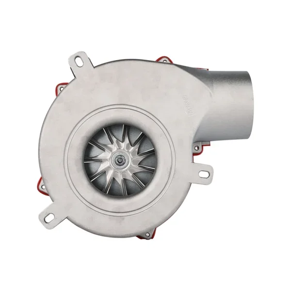
Use the compact blower reference for a defined heater air-circuit enquiry. Confirm medium, temperature, sealing and the full appliance sequence for the proposed model.
Explore this fan family →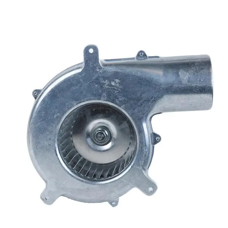
AC gas-blower reference
Review the AC housing and motor arrangement against the tube-heater installation. Any extraction duty requires its actual medium and thermal conditions to be specified.
Explore this fan family →Product images show family configurations. Request the drawing, curve and electrical information for the exact model being considered.
What should your fan enquiry include?
Share these application details so the fan proposal can be reviewed against your equipment.
Bring the equipment context to the fan review.
A drawing, the operating condition and a clear control requirement make the proposed configuration easier to compare. For a replacement, include the existing nameplate and wiring details.
Discuss your application →Reference material for the next step.
Compare available gas-blower configurations, then request the complete model drawing and performance curve for the defined appliance air path.
AC series catalogue · PDFAC gas-blower catalogue ↗Use the AC family references to discuss supply and mounting options; confirm the specific model’s medium and temperature limits.
Engineering checklistFan replacement controls checklist ↗Record electrical, control and mechanical interfaces when comparing an existing fan with a proposed replacement in the complete equipment.
Catalogs support initial selection. Confirm the current specification and approved configuration with the project team.
Why must the blower position be specified?
Its position determines the medium, temperature and air-path conditions it encounters. An intake-air proposal can differ substantially from an extraction-position proposal. Mark the blower on the heater drawing and supply the conditions at that location so the correct complete-model requirements can be reviewed.
Can an existing blower be matched from a photograph?
A photograph can help identify the general housing arrangement, but it cannot establish the duty point, control behaviour or exposure limits. Supply the part number, interface drawing, pressure-flow requirements and operating conditions. The proposed replacement also needs assessment within the complete heater sequence.
Continue with the equipment you are designing.
Share your equipment and operating conditions.
Send the drawing, target duty and project timing. Add the existing fan details when you need a replacement.