
Fan Replacement Checklist: 9 Checks Before You Order
A replacement fan needs to match the installation, the electrical supply, the control system and the required operating point. Start with a candidate model, resolve the nine checks below, then validate the sample in the intended equipment.
Check the assembly, then the drawing

Keep the model and revision together
Start with the RLM series catalog when considering this product family. Identify the full proposed model and obtain its current drawing before comparing fit or performance.
View RLM series catalog (PDF)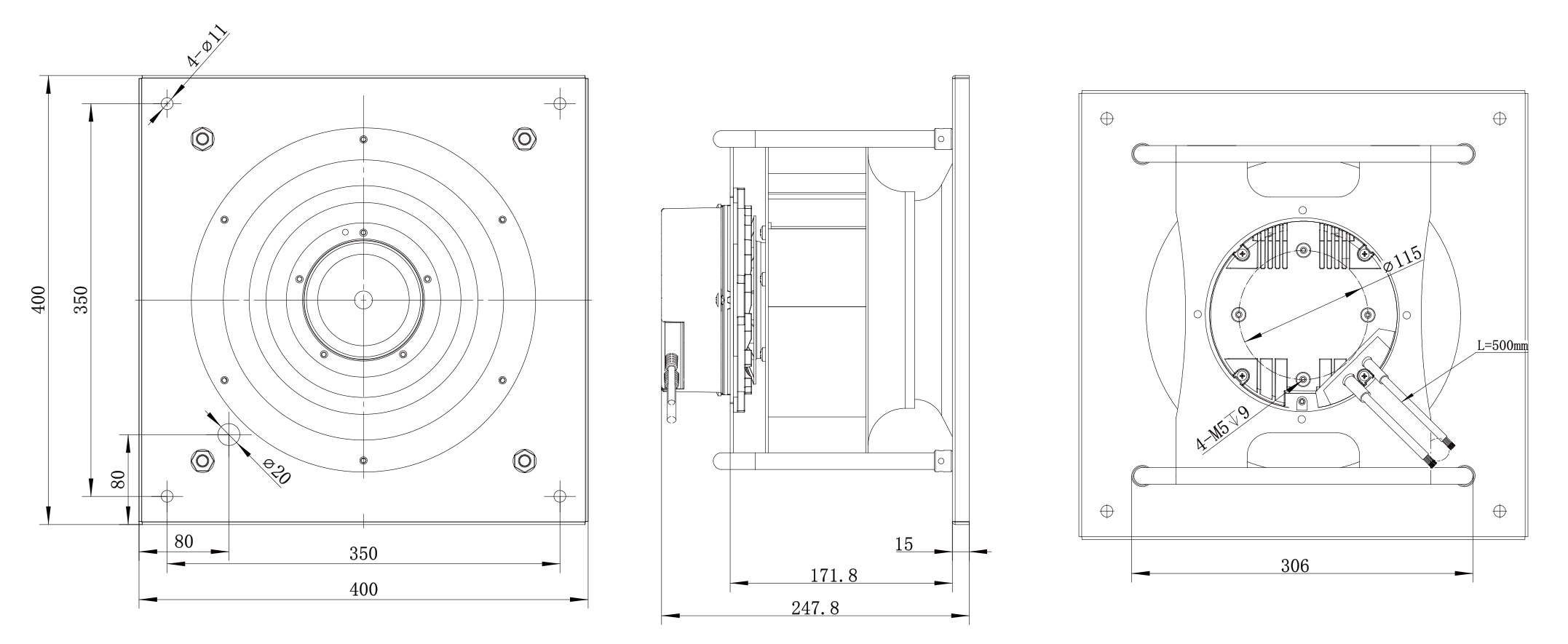
Nine checks for a replacement assessment
Record each item as confirmed, awaiting information or requiring sample validation. Keep the drawing and specification revision with the assessment so the result applies to the configuration being ordered.
| Check | What to confirm | Useful evidence |
|---|---|---|
| 1. Exact configuration | Full model, suffix and revision; approved drawing and specification. | Nameplate photograph and revision-controlled documents. |
| 2. Installation dimensions | Overall envelope, mounting holes, shaft or motor position, and service access. | Dimensioned drawing and photographs of the available space. |
| 3. Air path and orientation | Airflow direction, rotation, inlet arrangement, obstructions and clearance. | Installation layout with inlet and outlet conditions. |
| 4. Operating point | Required airflow at the relevant static pressure and speed. | Duty-point requirement and comparable performance curves. |
| 5. Supply and motor | AC or DC supply, voltage, phase, frequency, motor type and electrical limits. | Supply specification and motor or fan nameplate. |
| 6. Command interface | Pinout and model-specific PWM, 0-10 V or communication requirements. | Controller output specification and fan interface document. |
| 7. Feedback and fault states | Speed feedback, relay states, communication status and loss-of-signal behavior. | Feedback definition, contact-state table and communication documents. |
| 8. Operating range | Ambient conditions, minimum starting command, stable low-speed range and noise requirements. | Application conditions and the proposed operating-range test. |
| 9. Sample acceptance | Installed fit, electrical and control operation, airflow, pressure and any required fault response. | Agreed test conditions, acceptance limits and recorded results. |
1. Can I replace a fan with another model that has the same diameter or mounting dimensions?
Matching dimensions are only the first check. Compare the complete model and revision, motor type, rated speed, supply, rotation, inlet arrangement and control interface. Two assemblies can share an outline while using different motors and speeds.
Specify the airflow required at the system's static pressure, then compare the relevant performance curves under equivalent conditions. Confirm the mounting, wiring and operation in the actual equipment before describing a candidate as a drop-in replacement.
2. What should I send for a replacement assessment?
Send the existing nameplate and full model number, the installation drawing or measured dimensions, and clear photographs of the fan compartment and connections. Include the supply voltage and frequency, the required airflow and static pressure, and the controller's output specification.
For a controlled fan, add the connector pinout, signal voltage, PWM frequency if applicable, feedback requirements and expected behavior when the command or power is lost. If an input is unknown, mark it as unknown so it can be resolved before the sample is specified.
3. Are PWM, 0-10 V and Modbus interchangeable options?
Do not treat these labels as interchangeable. Use the approved specification for the exact fan and controller combination. For PWM, confirm signal voltage, frequency, duty-cycle range and the input circuit. For 0-10 V, confirm the reference connection, input limits and the relationship between the command and speed. For Modbus, obtain the communication settings and register map.
Also distinguish the command input from speed feedback or an alarm output. Wire color alone is not a sufficient identification method, and an unchecked option on a generic approval form does not confirm that the option is included.
4. Does a low command value guarantee that the fan will start and run steadily?
A speed-control label does not specify the minimum starting command or minimum stable speed. Ask for those limits for the selected model, including any stop threshold, startup behavior and response to a missing signal.
For a low-speed application, agree a test using the intended power supply, controller and installed airflow resistance. Record cold and warm starts, commanded value, measured speed and any unstable operation. Confirm the acceptable operating range from those results before setting the minimum command in the equipment controller.
5. What information is needed to integrate a Modbus fan?
Request the protocol and version, device addressing, baud rate, parity, register map, scaling and read/write permissions. Confirm which registers command speed and which report actual speed, operating state or faults. Define what happens after a communication timeout and after power is restored.
Then verify a basic command-and-feedback sequence with the intended controller and fan revision. An RS485 connection or a Modbus RTU label establishes part of the interface description; it does not replace the register map or demonstrate compatibility with every controller.
6. Does a closed alarm contact prove that a fan is powered and healthy?
Check the contact-state table for the exact model. A relay contact may have the same state during normal operation and when the fan is unpowered, so one contact state alone may not distinguish those conditions.
Define the required indications for normal running, commanded stop, loss of power and a declared fault. Confirm the contact rating and wiring, then verify each relevant state. Where the application needs to distinguish more states than the relay provides, agree the additional speed feedback, communication status or power-status input before commissioning.
7. Will a speed-controlled fan keep airflow constant as a filter loads?
Do not infer constant-airflow operation from the presence of PWM, 0-10 V or a communication interface. Confirm the control method, the airflow measurement or estimation method, and the fan's available operating range.
For a filter application, define clean, intermediate and design-final pressure conditions. At each condition, record airflow, speed and input power in the intended assembly. Check whether the controller can still meet the airflow target without exceeding the agreed speed or power limits. The resulting test defines the usable range; the interface name alone does not.
8. Does adding one extra fan automatically provide N+1 redundancy?
Specify the required airflow and pressure with one fan unavailable. Assess the remaining fans at that condition, including their speed and power limits, the airflow path through the stopped module, and the controller's response.
For a fan wall, agree a test that records total airflow, pressure, fault indication and recovery time after one module is unavailable. Include the relevant loaded-filter condition if filters are part of the system. A single fan's alarm output is one input to this assessment; it does not establish the array's remaining cooling capacity.

Send your operating conditions
Share the existing model or drawing, required airflow and pressure, available installation space, power supply, and controller details. Mark missing values as unknown. State whether the priority is replacement fit, low-speed operation, filter compensation or operation with one fan unavailable.
Use the customer information checklist to organize the details. These inputs define what must be checked in the specification and what must be demonstrated by the sample.
Related selection resources
The LONGWELL cross-reference guide and EC fan cross-reference table can help locate models for review. Apply the checks above to the exact model, controller and installation before confirming the replacement.
Related video: AHU retrofit selection
Customer Information Checklist for a Fan Replacement
Complete what you know and mark other entries Unknown or Not applicable. Do not enter zero to represent an unknown value. For the first review, start with the nameplate, application, installation details, power supply and controller information. Operating-point and interface gaps must be resolved before the final configuration is confirmed.
中文填写说明:首轮可先提供铭牌、用途、尺寸/安装照片、供电和控制器资料。暂不掌握的数据请写“未知”,不适用写“不适用”;不要用0代替缺失。风量和压力请注明是设计值还是实测值,并标明测量位置。以下为工程选型资料,不要求提交报价或财务信息。
| Stage | Field | What to provide | Required when | Unit | Your information / 您填写 |
|---|---|---|---|---|---|
| Initial review | Existing fan identification / 原机识别 | Full model, suffix, revision and nameplate photograph | Required for replacement | ________________ | |
| Initial review | Application / 设备用途 | Equipment type and reason for replacement | Required | ________________ | |
| Initial review | Installation / 安装空间 | Overall size, mounting holes, inlet and outlet arrangement, photographs | Required for fit review | mm | ________________ |
| Initial review | Supply / 供电 | AC/DC, voltage; phase and frequency if AC | Required before sample specification | V / Hz | ________________ |
| Initial review | Controller / 控制器 | Controller model and output specification | If controlled | ________________ | |
| Duty point | Airflow / 风量 | Required airflow at the stated pressure; identify measured or design value | Required for performance selection | m3/h or CFM | ________________ |
| Duty point | Pressure / 压力 | Required static pressure and where it is measured | Required for performance selection | Pa or inH2O | ________________ |
| Duty point | Operating conditions / 工作条件 | Air temperature, altitude if relevant, and operating speed or load range | Required for final assessment | C / m / rpm | ________________ |
| Installation | Air path / 风路 | Rotation and airflow direction, inlet cone, nearby obstructions, filter or coil | Required for installed review | ________________ | |
| Installation | Environment / 环境 | Humidity, dust, moisture exposure and any stated protection requirements | Required for final assessment | ________________ | |
| Installation | Noise requirement / 噪声要求 | Limit, operating point, distance and measurement conditions | If a noise limit applies | dB(A) / m | ________________ |
| Control | Pinout / 接线 | Connector identification, pin numbers and each function | For powered or controlled connections | ________________ | |
| Control | PWM command / PWM输入 | Signal voltage, frequency, duty range and input/output circuit type | PWM only | V / Hz or kHz / % | ________________ |
| Control | Analog command / 模拟输入 | Voltage range, reference connection and command-to-speed behavior | 0-10 V or other analog control only | V | ________________ |
| Control | Communication / 通讯 | Protocol/version, address, baud rate, parity, register map, scaling and access permissions | Communications control only | ________________ | |
| Control | Speed feedback / 转速反馈 | FG/tach signal type, pulse definition, output circuit and controller input requirements | If speed feedback is used | Pulses/revolution / V | ________________ |
| Control | Relay and alarms / 继电器与报警 | Contact rating and expected states during running, stop, power loss and fault | If fault feedback is required | V / A | ________________ |
| Control | Low-speed behavior / 低速行为 | Minimum requested speed, start/stop thresholds, cold/warm starts | If low-speed operation is required | rpm / command units | ________________ |
| Control | Lost signal and restart / 失信号及恢复 | Required behavior after command loss, communication timeout and power restoration | If automatic control is used | s where relevant | ________________ |
| Conditional test | Filter loading / 滤网阻力变化 | Clean, intermediate and design-final pressure; airflow target and control method | Filter/constant-airflow assessment only | Pa / m3/h | ________________ |
| Conditional test | One fan unavailable / 单台不可用 | Array count, required remaining duty, stopped-module airflow path and allowed recovery time | Fan-wall redundancy assessment only | Pa / m3/h / s | ________________ |
| Sample acceptance | Acceptance criteria / 样机验收 | Required checks, measurement conditions and pass limits for this installation | Required before acceptance testing | ________________ |
Attach the available drawing, nameplate and controller documents. Identify their revisions and mark the items still to be confirmed.