
Fans for Solid-Fuel Combustion and Room-Air Delivery
A solid-fuel heater can use different fans for combustion air, extracted gases and warm-air delivery to the room. Start with the exact function and exposure of each circuit. LONGWELL blower and cross-flow references help organise a model enquiry without treating those air paths as interchangeable.
Separate combustion airflow from room-air circulation
Use the heater drawing to identify where air enters, where it passes the heat exchanger and whether a fan is exposed to combustion products. Specify the applicable temperatures, pressure and cleaning conditions for each position. Room-side fan selection can then proceed independently of a combustion or exhaust-blower review.
Why Biomass Grates Need Two Air Supplies
A grate-fired biomass heater needs oxygen in the fuel bed and in the gases released above it. Separate primary and secondary supplies deliver air to those different locations. This example illustrates those paths within the wider range of solid-fuel heating applications.
Follow the air through the process
Primary air enters beneath the grate
A supply feeds the under-grate space. Air rises through actual grate openings and gaps between fuel pieces, bringing oxygen into the bed.
Heating releases gases above the bed
Moisture leaves as the biomass heats, and combustible gases rise into the space above the fuel. The solid bed is only part of the combustion process.
Secondary jets meet those gases
Separate nozzles above the grate supply oxygen and promote mixing with the rising gas stream.
Match the two deliveries to the fuel
Bed resistance and secondary-nozzle resistance are different duties. Their air deliveries must suit the fuel and firing range rather than simply increasing both flows.
Airflow function
- Supply primary air through grate openings into the fuel bed.
- Supply secondary air above the bed to meet the rising combustible gases.
- Match each branch’s pressure-flow and control range to the firing conditions.
What can change the result
- Air delivered to the wrong location can leave the bed or above-bed gases poorly served.
- A change in fuel or bed conditions can alter the primary-air requirement.
- Increasing both air supplies without a coordinated firing strategy does not establish good combustion.
Start with the complete air path
Share your layout and the information you already have. Unknown values can be identified before a configuration is selected.
Match the fan to this air path
Review LONGWELL LW4-72 industrial centrifugal families for suitable fresh-air supply duties. Define the under-grate and secondary-nozzle operating points separately and confirm the full appliance design.
Where it sits
On a fresh-air supply feeding either the under-grate plenum or the secondary-air nozzles. Each branch is selected against its own required delivery and resistance.
Why consider this configuration
The documented industrial centrifugal family includes furnace-related ventilation. Reviewing primary and secondary supply duties separately keeps the bed and above-bed mixing functions clear.
Check the result in your equipment
Application questions
Why not send all the air beneath the grate?
Air in the bed supports the solid fuel. The gases released above it also need oxygen and mixing, supplied by the separate secondary path.
Does secondary air replace the primary-air fan?
It serves a different location. The required balance depends on the fuel, grate and firing conditions.
Does this video apply to every solid-fuel heater?
It illustrates a grate-fired biomass arrangement with two air supplies. Other appliances need their own air-path and fan-duty review.
Discuss your combustion-air branches
Send the grate and secondary-nozzle layout, fuel specification and firing range. Include the required primary and secondary flow/pressure duties and inlet-air conditions.
A layout, installation photos or your existing model is enough to start the discussion.
Identify the combustion or extraction duty
Mark the blower position on the heater air-path diagram and state the medium it handles. Record airflow and pressure through ignition, steady firing and shutdown. If the proposed position is in an exhaust path, provide its temperature and contamination conditions explicitly for a model-specific assessment with the equipment manufacturer.
- Fan position and handled medium
- Ignition, firing and shutdown duty
- Temperature and particulate exposure
Keep the warm-air outlet in view
For room-side convection, describe the heat-exchanger passage and discharge grille separately from the combustion circuit. A cross-flow format can be evaluated where a long outlet and shallow installation space are required. Measure the resistance of the intended air path and establish motor temperatures during normal operation and heat soak.
- Room-air path and outlet length
- Heat-exchanger and grille resistance
- Motor temperature during heat soak
Design for cleaning and control
Identify ash, dust or deposits that can reach the selected fan position and explain the intended cleaning access. Specify the appliance’s fan command and feedback requirements, including response when the expected airflow is not established. Agree inspection and maintenance details using the documentation for the selected complete assembly.
- Contaminants reaching the fan
- Access for inspection and cleaning
- Control sequence and airflow response
Match the fan family to the equipment.
Compare the proposed model at the required airflow and pressure, then check the installation and control interface.
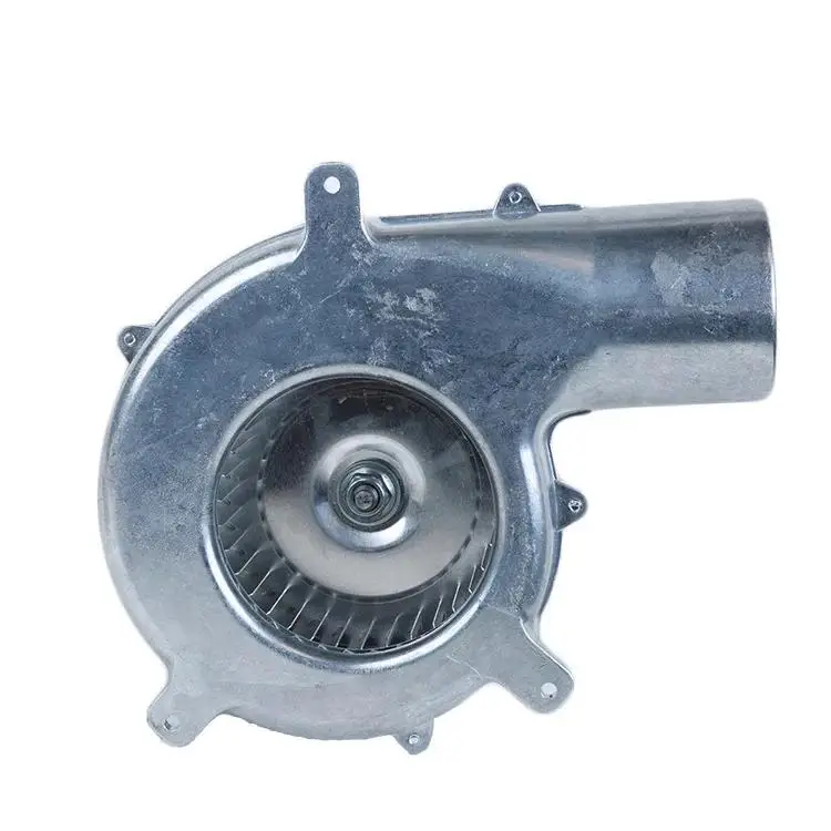
AC gas-blower reference
A blower reference for a defined combustion-air configuration review. Ask for the specific model’s temperature, contamination and mounting limits before selecting the heater arrangement.
Explore this fan family →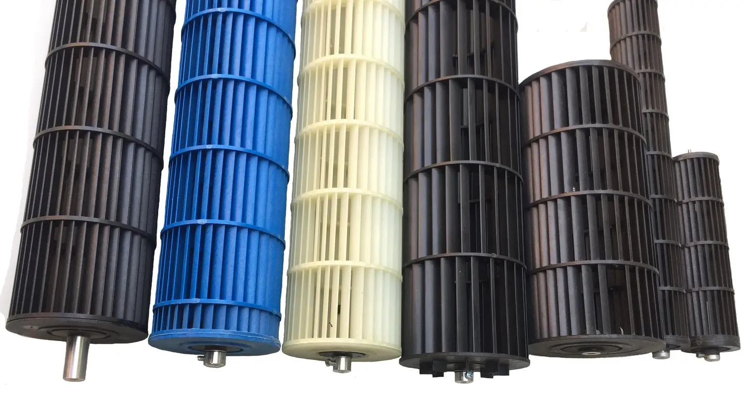
Cross-flow fan families
Review cross-flow formats for a separate room-air convection path. Specify the outlet length, heat-exchanger resistance and motor temperature at the proposed mounting position.
Explore this fan family →Product images show family configurations. Request the drawing, curve and electrical information for the exact model being considered.
What should your fan enquiry include?
Share these application details so the fan proposal can be reviewed against your equipment.
Bring the equipment context to the fan review.
A drawing, the operating condition and a clear control requirement make the proposed configuration easier to compare. For a replacement, include the existing nameplate and wiring details.
Discuss your application →Reference material for the next step.
Use the AC family references to discuss supply and mounting options; confirm the specific model’s medium and temperature limits.
Cross-flow series · PDFCross-flow fan catalogue ↗Compare rotor lengths and motor arrangements, then request model-specific airflow, temperature and mounting information for the proposed outlet layout.
Engineering checklistFan replacement controls checklist ↗Record electrical, control and mechanical interfaces when comparing an existing fan with a proposed replacement in the complete equipment.
Catalogs support initial selection. Confirm the current specification and approved configuration with the project team.
Can the room-air fan also be used in the flue path?
The two positions have different exposure conditions. A room-air selection does not establish suitability for hot combustion products, ash or condensate. An exhaust-path proposal requires the actual medium, temperatures, cleaning conditions and model-specific limits to be reviewed with the heater manufacturer before selection.
Why include shutdown conditions in the fan brief?
Conditions can change when firing stops and the surrounding heater components remain warm. Describe the required fan sequence and temperature exposure during that period, as well as normal operation. This helps the model review address the complete operating cycle and the intended controller behaviour.
Continue with the equipment you are designing.
Share your equipment and operating conditions.
Send the drawing, target duty and project timing. Add the existing fan details when you need a replacement.