
Fans for Drive Electronics and Control Cabinets
Drive electronics release heat inside cabinets that may have limited space, filters and nearby machine components. Define the losses at continuous and peak load before choosing a fan. This page addresses cooling around drives and controllers; propulsion, positioning and actuator selection remain separate equipment tasks.
Explore the applications in this industry.
Translate the drive duty cycle into a cooling brief
A drive’s output rating is not the same as the heat its enclosure must remove. Use specified or measured losses, the permitted electronics temperature and the installation layout to establish a cooling requirement. Then review airflow resistance, electrical interfaces and the fan’s behavior across the machine operating cycle.
Separate output power from cabinet heat
Provide the losses of drives, power supplies and other cabinet electronics during continuous duty, acceleration and idle operation. Identify local hot spots and their temperature limits. Use that information with the enclosure arrangement to define the airflow task, rather than selecting a fan from the machine’s rated motor power.
- Electronics losses by machine operating mode
- Component limits and local hot spots
- Cabinet layout and allowable ambient conditions
Review the installed airflow path
Show the filter, louvre, heat-sink and cable arrangements, including where heated air leaves the cabinet. Check whether internal partitions or neighboring equipment encourage recirculation. Compare candidate fans at the required resistance and available depth, retaining enough clearance for the inlet and for service access.
- Clean and loaded-filter operating points
- Inlet/outlet locations and cable obstructions
- Mounting depth and maintenance clearance
Integrate cooling controls and fault handling
Specify the fan’s supply and control interface independently from the drive’s motor-output connections. Define normal speed operation, any demand signal and the required feedback. Agree how the machine controller responds to loss of cooling, then test the selected fan and controller through the relevant operating states.
- Separate fan supply and drive output
- Speed input and rotation or alarm feedback
- Loss-of-cooling response and restart behavior
Match the fan family to the equipment.
Compare the proposed model at the required airflow and pressure, then check the installation and control interface.
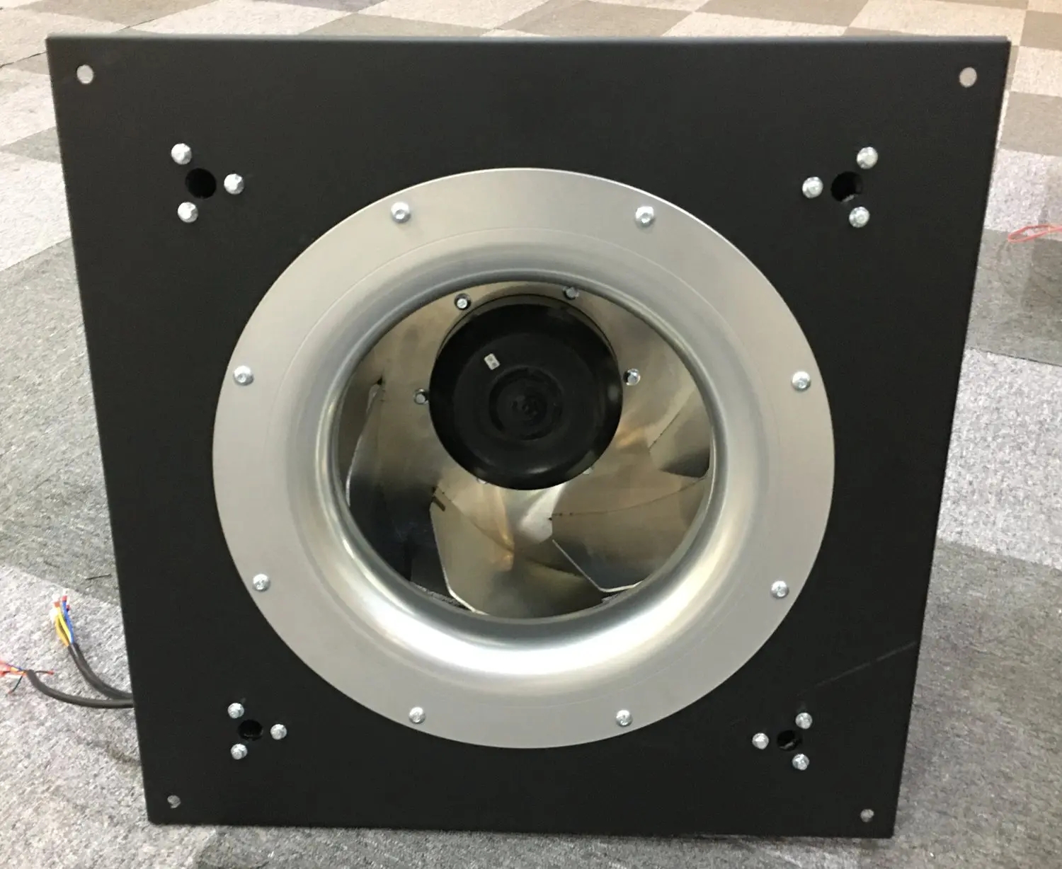
Panel-mounted centrifugal options
Review centrifugal fan arrangements for drive cabinets with filters and restrictive air paths. Confirm the mounting panel, inlet conditions and selected control configuration for the enclosure.
Explore this fan family →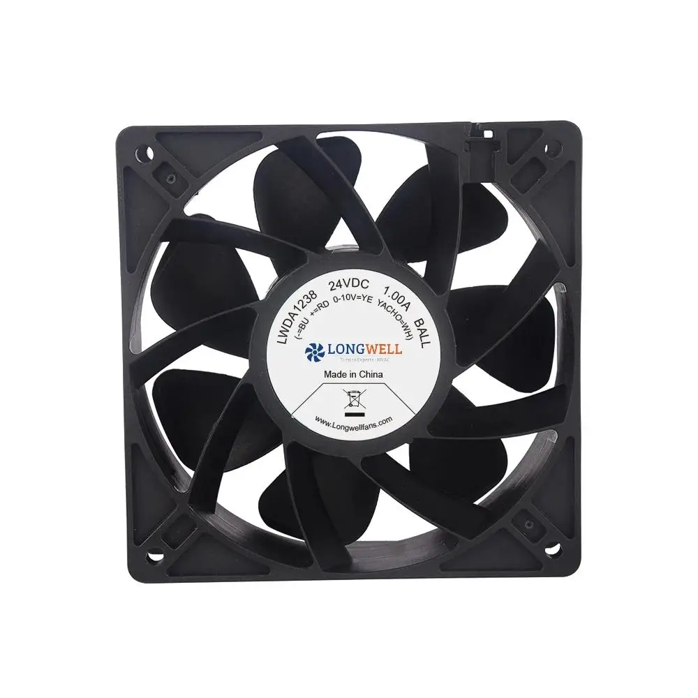
Compact DC axial fans
Review compact DC axial formats for individual drives, power supplies or smaller cabinets. Confirm heat-sink resistance, supply tolerance and the required feedback on the proposed version.
Explore this fan family →Product images show family configurations. Request the drawing, curve and electrical information for the exact model being considered.
What should your fan enquiry include?
Share these application details so the fan proposal can be reviewed against your equipment.
Bring the equipment context to the fan review.
A drawing, the operating condition and a clear control requirement make the proposed configuration easier to compare. For a replacement, include the existing nameplate and wiring details.
Discuss your application →Reference material for the next step.
Compare centrifugal component formats and request the curve and mounting drawing for the proposed drive-cabinet operating point.
Engineering checklistFan replacement and controls checklist ↗Record fan wiring and feedback separately from the motor-drive interface when assessing a replacement or controller integration.
Catalogs support initial selection. Confirm the current specification and approved configuration with the project team.
Can motor power be used directly as the cabinet cooling load?
Motor output power and heat released by the drive electronics are different quantities. Obtain drive and auxiliary-component losses for the intended operating modes, then assess how that heat leaves the cabinet. Use the resulting thermal and airflow requirement to evaluate a fan.
Does a cooling-fan proposal include the motion-control system?
The proposal concerns the fan’s airflow, installation and electrical interface. Positioning accuracy, torque control, braking and actuator behavior belong to the machine’s drive design. Define any interaction through documented control signals and evaluate loss-of-cooling behavior with the equipment integrator.
Continue with the equipment you are designing.
Share your equipment and operating conditions.
Send the drawing, target duty and project timing. Add the existing fan details when you need a replacement.