A fan performance curve is a map, not a promise that the fan can operate equally well everywhere shown. The connected system chooses one address on that map. Buying from maximum airflow means selecting from the edge where external pressure is near zero—not from the point a real duct, filter, coil, or machine may require.
A defensible selection begins with a duty point, finds the intersection between fan and system curves, and then reads pressure, power, efficiency, sound, and operating limits at that same airflow. Every curve must also match the project’s pressure definition, speed, air density, test arrangement, and power boundary.
Read the Axes and Test Conditions First
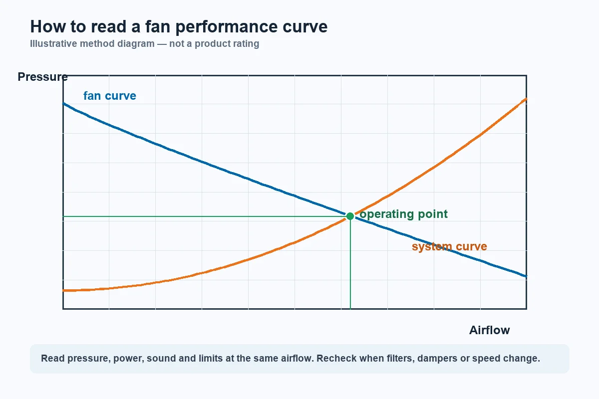
Airflow normally appears on the horizontal axis. Fan static pressure or fan total pressure appears on the vertical axis. Those pressure definitions are not interchangeable, so the selected curve must use the same definition as the project specification.
Before reading values, confirm rotational speed, air density, inlet and outlet test arrangement, and the exact fan configuration. Determine whether a power curve represents shaft power, motor input, or complete electrical input. Otherwise, two charts that look similar may describe different boundaries.
In a teaching example, the required duty is 5,000 cubic metres per hour at 600 pascals. The flow and pressure form one point; airflow by itself cannot select a fan. Any accompanying values such as 1.8 kilowatts or 78 percent efficiency are illustrative reading points, not universal product ratings or guarantees.
Find the Fan-and-System Intersection
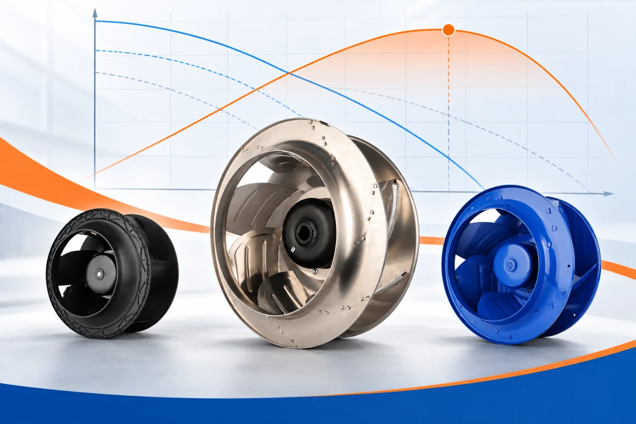
The descending line is the fan pressure curve. The rising line represents the resistance of ducts, fittings, filters, coils, grilles, and process components as airflow changes. The installed operating point is where those two curves intersect.
The point can move. A loaded filter or closing damper raises system resistance, steepening the system curve and generally shifting operation toward lower airflow and higher pressure. A more open path moves the intersection in the opposite direction. The fan does not remain at the original design dot when the system changes.
Define clean, loaded, minimum, normal, and maximum conditions where relevant. Each credible system curve should intersect an available fan or speed curve within a stable and permitted region. For a deeper reading sequence, use the centrifugal fan curve guide alongside the project-specific curve rather than relying on a single catalog label.
Read Every Performance Layer at One Airflow
At the operating airflow, move through each layer of the data sheet. First confirm that the pressure curve reaches the required value. Then read absorbed power so the motor, controller, and electrical supply have appropriate margin. Maximum input power elsewhere on the curve is not the duty-point input.
Check efficiency at the operating point rather than relying on a headline peak. Review sound data at the same speed and duty, with the same measurement quantity and test boundary. Finally, confirm current, temperature, speed, motor limits, and control range.
A candidate that crosses the duty only near an unstable region needs additional review or rejection. Another may reach the point only with heavy throttling or at an inefficient extreme. The physically largest fan is not automatically the best selection.
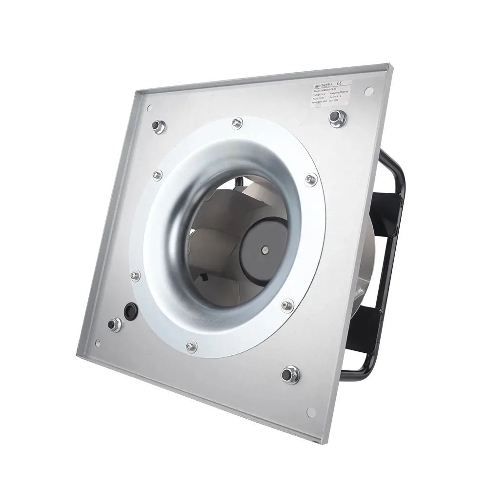
LONGWELL curve records distinguish exact fan configurations and model suffixes. Request the current pressure and power curves for the proposed suffix and speed; a product photograph or family page cannot supply those operating values.
Use Speed Curves and Fan Laws Carefully
Variable speed produces a family of performance curves. For the same fan under appropriate similarity conditions, airflow changes approximately with speed, pressure with speed squared, and power with speed cubed. These relationships are useful for preliminary screening.
They do not override motor heating, controller current, maximum permitted speed, air-density changes, or the real system curve. The intersection must be recalculated at each important speed. Confirm minimum command, stable operation, power, and sound throughout the intended control range.
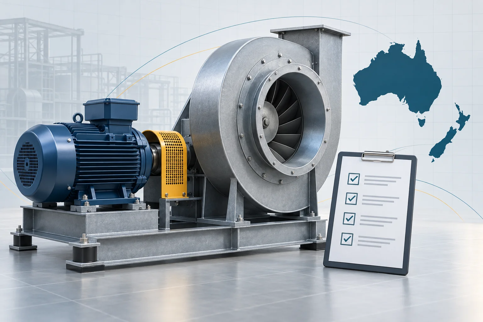
Do not apply one universal percentage to define a safe operating zone. Use the manufacturer’s permitted operating region for the exact fan, speed, and configuration, especially near a pressure peak or free-delivery end of a curve. If you are still collecting inputs before model comparison, the EC fan selection checklist is a safer starting point than guessing from diameter or maximum CFM.
Account for Installation and Commissioning
A laboratory curve belongs to a stated test arrangement. A tight inlet elbow, blocked intake, poor discharge clearance, dirty filter, or downstream obstruction can create system effect and move installed performance away from the catalog expectation. Preserve the required clearances and transitions or include the additional loss in the system model.
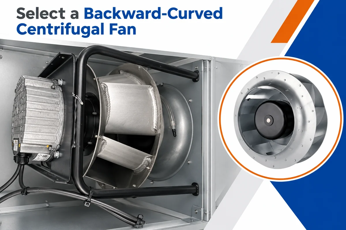
A practical workflow is to define airflow, pressure, density, and worst-case resistance; calculate the system curves; overlay fan and speed curves; read pressure, power, efficiency, sound, and limits at every important intersection; and then verify mechanical, electrical, and control interfaces. Product-family pages such as backward-curved centrifugal fans or centrifugal blower fans are useful only after the duty and evidence boundary are defined.
Commission the installed system by measuring airflow or a validated proxy, pressure, electrical input, sound, vibration, and control response. The right fan is the one whose complete curve family meets every required operating point inside a stable, efficient, allowable envelope—not the one with the largest maximum-flow number.