Select a combustion-air blower from a duty schedule, not from burner kilowatts or a free-air number. The schedule must state the required airflow, the pressure the blower has to overcome, the air condition used for that airflow, and the operating states from light-off to high fire. Without those four pieces, a model comparison is still a guess.
This is a procurement workflow, not a burner design. Fuel/air settings, combustion limits, purge logic, and safety devices belong to the burner or appliance design and must be confirmed by qualified combustion personnel against the manufacturer’s instructions and applicable rules. A blower change is never a reason to bypass an interlock.
Start with a schedule a supplier can actually use
Ask the burner or appliance engineer for the air requirement at light-off, low fire, the usual operating point, and high fire. Keep the stated reference condition with every airflow value. Temperature, altitude, humidity, and preheated air can change the volume that carries the required mass of oxygen.
Do not substitute a universal “air per kilowatt” rule or a fixed excess-air percentage. The U.S. Department of Energy’s process-heating guidance makes the important point: the appropriate excess air depends on the fuel, burner, process conditions, and process temperature. Use the approved combustion calculation and measured commissioning criteria for the real equipment.
| RFQ field | What to record | Why it matters |
|---|---|---|
| Operating states | Light-off, low, normal, and high-fire airflow | One high-fire point does not prove turndown control |
| Air basis | Actual or stated reference volume, temperature, pressure, altitude, humidity | Prevents unlike airflow values being compared |
| Pressure | Required static or total pressure at the same flow | Free-air capacity is not installed capacity |
| Power and control | Supply, starting method, command, feedback, and protection | Defines electrical and controls compatibility |
| Mechanical interface | Flanges, rotation, orientation, envelope, and service clearance | Separates physical fit from performance |
| Acceptance | Curve revision, test basis, combustion checks, and interlock tests | Creates a release record rather than a verbal match |
Draw the air path before adding pressure
Mark the selection boundary from the combustion-air inlet to the chamber. A typical path may include an inlet screen or filter, silencer, duct, elbows, the blower, a damper or venturi, a register, and the burner head. Chamber pressure also belongs in the ledger. Use component data or calculated losses at the required flow, and keep the pressure convention consistent.
Then test named scenarios: clean and dirty filter, minimum and maximum chamber pressure, and relevant ambient or inlet-air extremes. This is more useful than hiding every uncertainty inside one blanket margin. A margin with no owner or condition can make the blower harder to control while leaving the real worst case untested.
Read the curve at the duty point
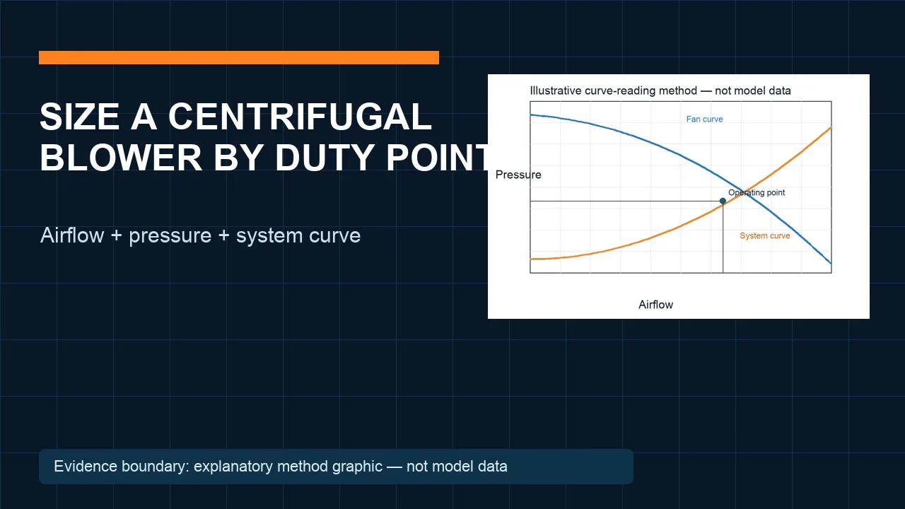
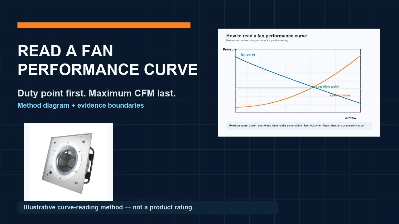
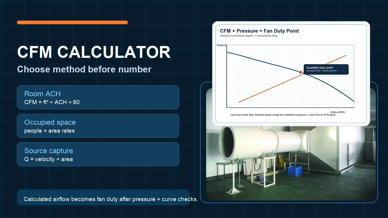
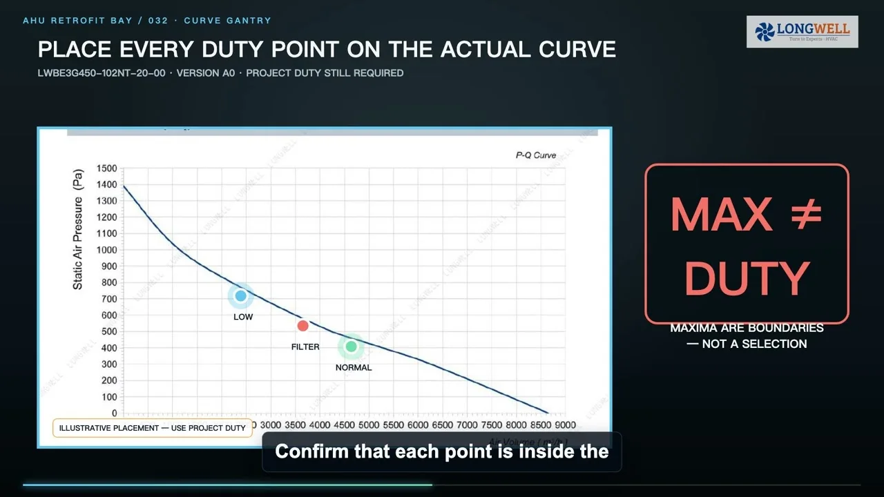
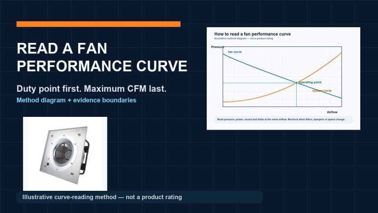
AMCA defines a duty point with airflow and pressure at a stated density. The installed operating point is where the fan curve and the system curve meet. Maximum airflow at zero pressure and shutoff pressure at zero airflow sit at the edges of a curve; neither is the working duty.
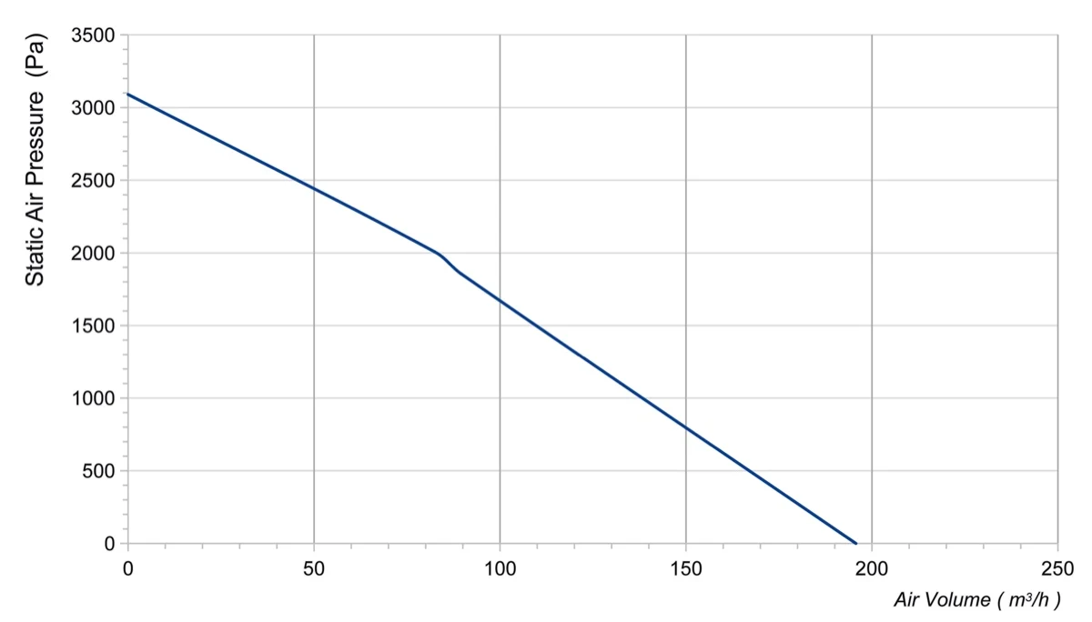
The image above is a real Longwell pressure–volume curve previously admitted for Topic036. It is useful for learning where airflow and pressure are read together. The isolated graphic does not show the complete speed, density, power, configuration, or revision context, so it is not being used here to approve a model or a project duty. For a fuller walkthrough, use the fan curve guide.
Check the full firing envelope and the control interface
Plot every required state on the applicable curve or selection data. Check absorbed power, speed limits, controllable range, and any unstable region at those same points. Burner turndown does not automatically equal blower-speed turndown: dampers, registers, chamber pressure, and the system curve can all change the relationship.
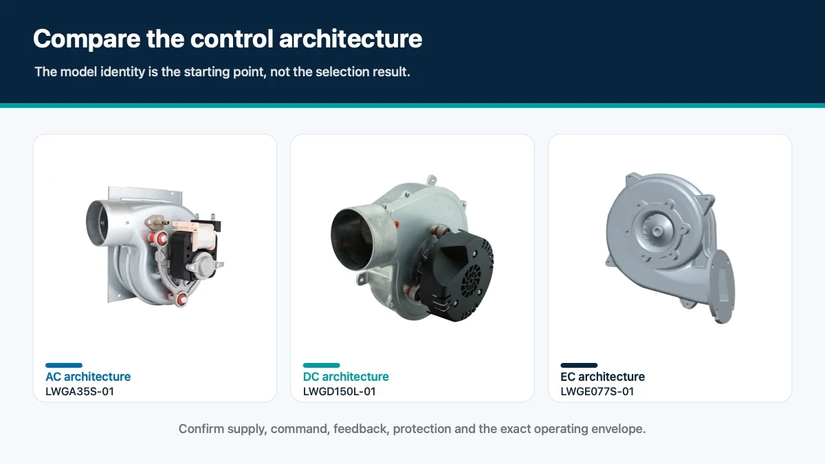
Longwell’s current LWGA35S-01 AC, LWGD150L-01 DC, and LWGE077S-01 EC pages are useful examples of distinct power and control architectures. These links establish product identity only. They do not say that the three models are interchangeable or that any one meets an unverified burner duty.
Keep combustion air separate from flue-gas exhaust
Define what the blower actually handles. This article concerns air supplied to combustion. A draft inducer or exhaust blower works on the flue-gas side, where temperature, condensate, corrosion, leakage, contamination, and material limits may be very different. A similar scroll housing does not make those duties equivalent.
If the system recirculates hot or contaminated gas into the air stream, write that condition explicitly. Obtain the manufacturer’s limits for the exact suffix and configuration. Do not infer temperature resistance, emissions performance, or approval from a catalogue family name or from a photograph.
For a replacement, lock the suffix before discussing “equivalent”
Record the original full model and suffix, drawing revision, rotation, mounting position, inlet and outlet geometry, connector pinout, supply, control signal, feedback, and protection. Also capture the old unit’s curve or test point and the air-proving device setting. A blower can bolt into the space and still shift the operating point or fail the control sequence.
Ask the supplier to return a marked curve and dimensional drawing for the proposed configuration. Differences should be resolved against the burner or appliance approval basis, not handled by adjusting a pressure switch until the machine starts.
Release the selection with a test plan
A purchase-ready package names the duty points, air basis, pressure ledger, curve revision, power and control limits, air-stream boundary, mechanical interfaces, and acceptance method. Commissioning should verify the specified firing states, combustion results required by the project, chamber pressure, air-proving response, purge and ignition sequence, flame safeguard, fuel shutoff, and loss-of-air response.
That record gives engineering, procurement, the burner supplier, and the blower supplier the same decision basis. If airflow, pressure, conditions, or safety acceptance is still missing, keep the candidate labelled for review—not selected.
Choose the right blower
Longwell manufactures 247 blowers in-house. Send airflow, static pressure and voltage — an engineer replies with a matching model, performance curve and price within one working day.