An electronically commutated blower can stop for reasons outside the motor: an absent run command, a supply problem, a disconnected harness, a stalled wheel, or an air path that cannot deliver the expected flow. A symptom helps decide what to check next; it does not identify a failed component. Use the exact appliance model, motor label, wiring diagram and service instructions before testing or ordering a replacement.
Start with the symptom you can actually observe
Record what happens during a normal call for heat, cooling or fan: does the blower remain still, try to start, run at an unexpected speed, or rotate while room airflow stays weak? Note any appliance fault code and whether the symptom is repeatable. Keep the observed behavior separate from a proposed cause. A single symptom can involve the thermostat or main board, the motor control, the motor, the wheel or the duct system.
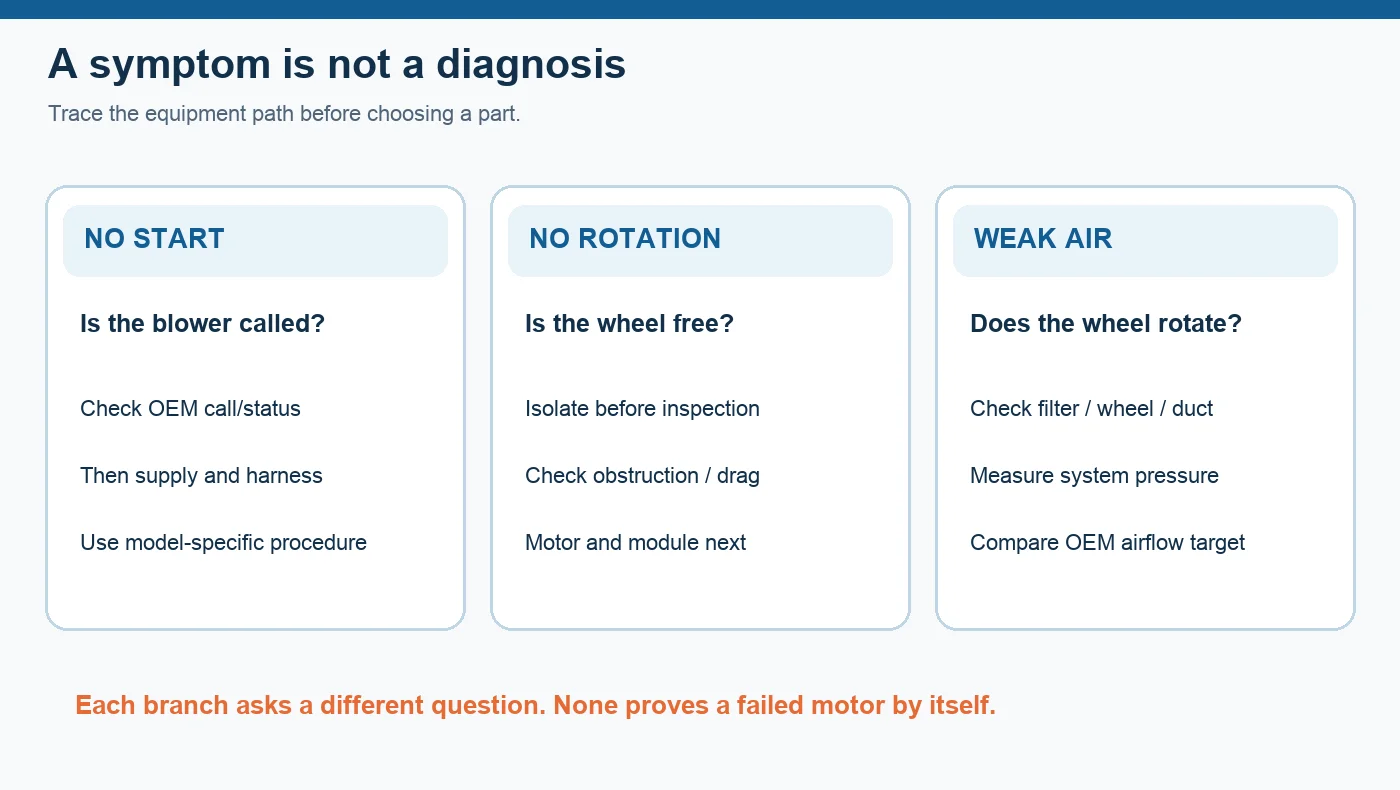
Figure 1 gives three practical branches. If the appliance never calls for the blower, replacing a motor cannot restore a command that is absent. If a call exists but the wheel does not rotate, the qualified technician can distinguish a mechanical obstruction from the electrical path by following the appliance procedure. If the wheel rotates but delivery is poor, inspect the filter, wheel and duct before treating speed or current as a motor verdict.
Confirm the command and supply using the appliance manual
ECM control interfaces are not interchangeable. Some systems use discrete inputs; others use a different control method and configuration. The correct connector pins, acceptable input range, fault-code meaning and test sequence belong to the exact equipment documentation. Ask whether the board is issuing the intended call, whether the harness is intact and whether the supply at the specified test point meets the OEM procedure. A generic voltage or resistance number copied from another motor can send the diagnosis in the wrong direction.
Live electrical testing and module removal belong to trained personnel using the documented service procedure. Servicing also requires control of unexpected energization and stored energy. The OSHA hazardous-energy guidance explains that safety boundary. This article is a decision map, not a substitute for the appliance service manual or a live-test instruction.
Inspect the wheel and the air path before condemning electronics
After safe isolation, a technician can inspect whether the wheel is obstructed, damaged or rubbing the housing, and whether filters and downstream passages are restricted. A wheel that turns during a test does not establish delivered airflow. Conversely, a dirty filter alone does not prove that the ECM is healthy. Keep the mechanical observation, the electrical observation and the measured system response as separate pieces of evidence.
For a low-airflow complaint, record the filter state, wheel condition and system-pressure measurements required by the appliance manual. Compare those results with the equipment’s intended operating range. The related blower-runs-but-no-airflow guide follows the air-path side of that question. Avoid inferring a fixed percentage loss or a universal motor-protection behavior from the symptom alone.
Decide whether the motor, control or system needs service
Once the command, supply and mechanical path are documented, use the motor manufacturer’s approved diagnostic sequence for that exact motor family. A control module may be separately replaceable on one design and integral on another. The connectors, programming, module pairing and available test tools also vary. For example, Regal Rexnord’s Genteq module installation guide names specific applicable motor families; that list should not be generalized to every ECM blower.
Do not treat an improvised module swap, a single winding reading or a hand-spin result as a universal pass/fail test. If the required reference values or tool are unavailable, the safe conclusion is that the component has not yet been isolated. Record the missing model data and obtain the OEM procedure rather than assigning a confident fault label.
Match a replacement to the whole assembly
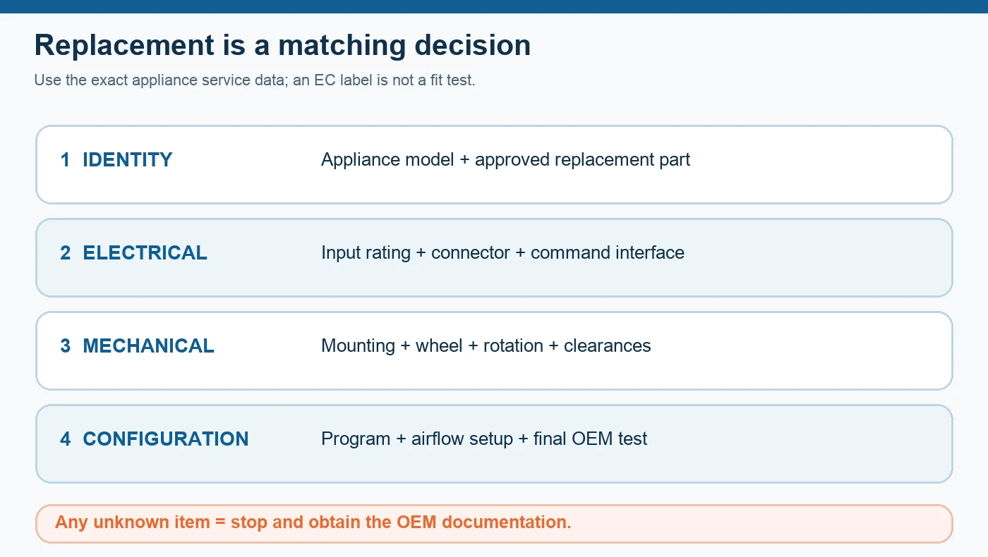
An “ECM” label describes a control principle, not a drop-in part number. Before ordering, match the appliance model and approved replacement identity, electrical input and connector, control interface, mounting and wheel geometry, direction of rotation, and any required programming or airflow setup. Figure 2 makes those four gates visible. An unknown gate is a reason to stop and request the relevant drawing or service record.
LONGWELL’s EC fan family is a useful starting point for a new OEM fan design conversation, but a family page does not establish that any model replaces a particular furnace blower. The company ECM(Q) catalog distinguishes multiple motor codes and supply variants; those distinctions support careful identification, not a blanket compatibility claim. For an existing appliance, the equipment maker’s approved replacement and configuration remain the controlling documents.
Verify the repair at the intended operating point
After an approved repair, the qualified technician should run the equipment through the operating modes specified by its manufacturer, confirm the fault code has cleared where applicable, and compare airflow or pressure with the appliance’s stated target. Document the final motor and controller identifiers, configuration and measured result. If the original complaint was low airflow, inspect the surrounding air path again; a new motor does not clean a restricted filter or correct a duct problem.
That sequence gives the buyer or service team a useful handoff: observed symptom, appliance and motor IDs, confirmed command and supply findings, wheel and duct findings, the OEM test used, and the final measured operating condition. It also makes future service less dependent on memory or a guess from one symptom.
Choose the right blower
Longwell manufactures 247 blowers in-house. Send airflow, static pressure and voltage — an engineer replies with a matching model, performance curve and price within one working day.