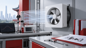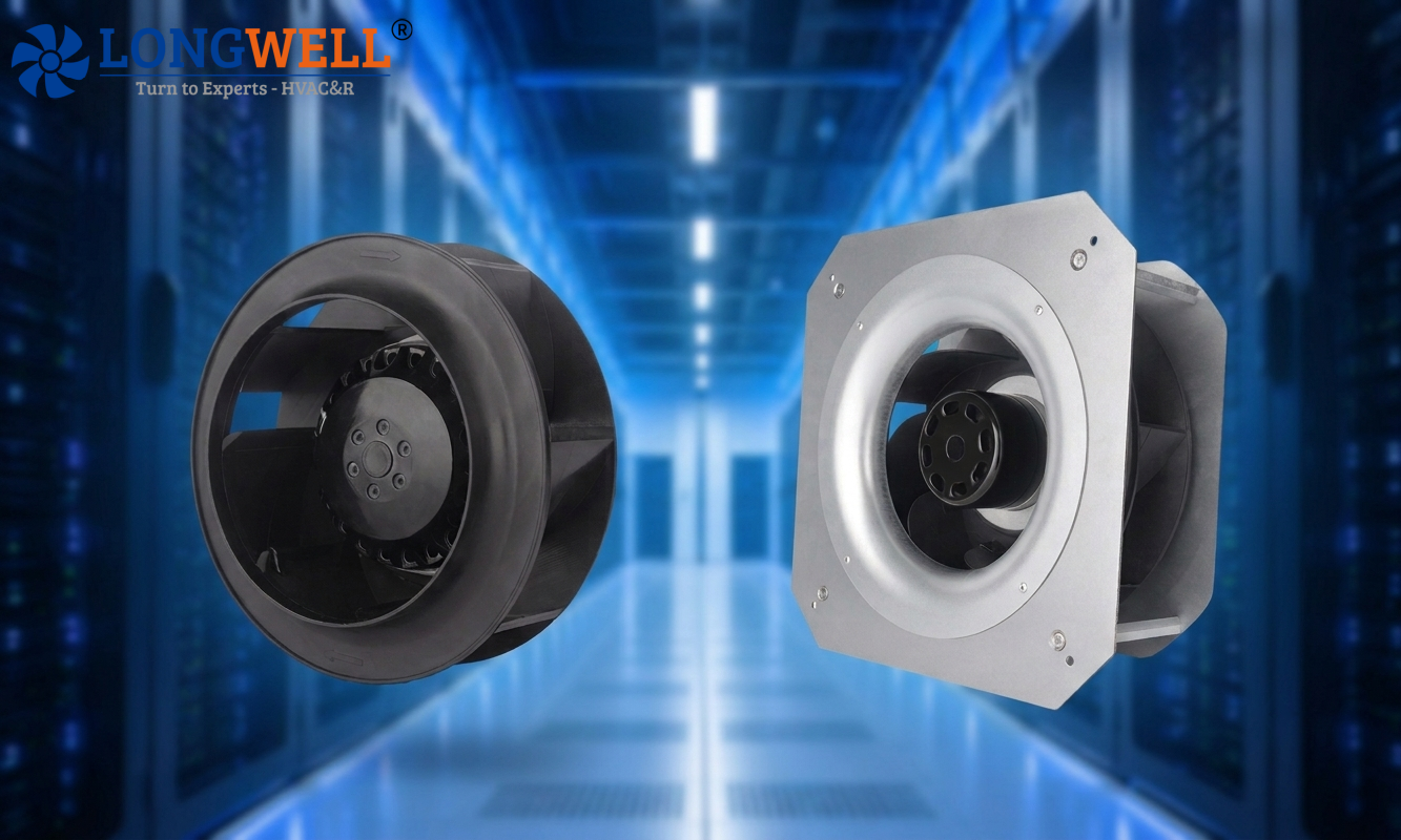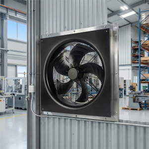
Parallel fans and fan walls are often used in modern HVAC systems, air handling units (AHUs), and data center cooling applications. Instead of using a large fan, a parallel fan arrangement or a fan wall uses multiple small fans to deliver required airflow. Two fans in parallel do not give you twice the airflow. Sometimes they give 20% more. Sometimes one of them stalls. And the difference is the not the fans. It is the air path, the layout, and the control.
This article puts the whole method in one place, in the order the work is done, and runs it on real fan data: how to define the duty, calculate what the path costs, combine the fan curves, lay the fans out, size the redundancy, and prove the result on the first unit. Every number below comes from a real worked example using LONGWELL test data for the LWBE3G450-188NT-21 EC plug fan (Ø450 mm backward-curved impeller).
What Are Parallel Fans and Fan Walls?
Parallel fans are two or more fans connected to a common air system, each fan in the parallel arrangement contributes to the required airflow. Parallel fans are used when one fan cannot meet the requirements of application airflow.
The fan wall is a structured arrangement of multiple fans installed side by side within a space or plenum. Typical fan wall configuration includes 2×2, 3×3, and 4×4.
Note: Fans connected in series and fans operating in parallel serve different purposes. “n” fans in series will increase pressure “n” times, while “n” fans in parallel will increase flow “n” times. Actual performance depends on the individual fan curves and system resistance.
4 Fundamental Principles That Determine Fan Selection for Fan Wall
A reliable fan wall design is more than just dividing the required airflow among several fans. Engineers or OEMs need to understand how the fans interact with the system, how air density affects performance, and how speed control changes airflow and energy consumption.
1. The Fan Does Not Determine the Airflow. The Operating Point Does.
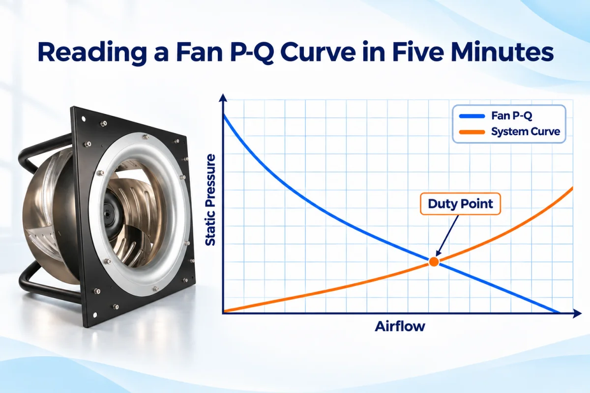
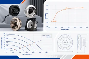
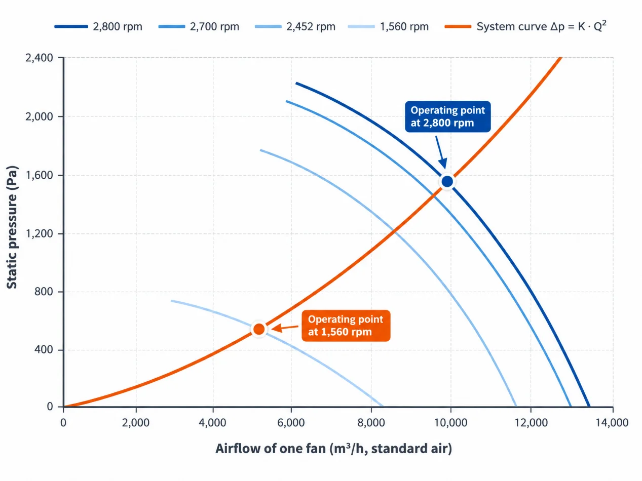
A fan’s performance curve describes the relationship between airflow and the pressure it can generate. A fan can deliver any point on its curve. The air path can pass a given flow at only one pressure. The system runs where the two curves cross.
A catalogue figure like “12,647 m³/h” is the free-blowing end of the curve at zero pressure. It never occurs in an installed system. If your selection process starts from a free-air figure and subtracts, you are selecting from fiction.
2. Pressure must be defined before it is compared
Static pressure, total pressure and “external static” are different quantities. A fan curve and a system calculation can only be combined if both use the same definition and the same two reference locations. To have a better understanding of fan performance curve and system pressure, you need to learn about the following terms:
- Static pressure (SP): The pressure exerted by the air, excluding the pressure associated with its velocity.
- Velocity pressure (VP): The pressure associated with air velocity.
- Total pressure (TP): The sum of static pressure and velocity pressure.
- External static pressure (ESP): The static pressure available to overcome resistance outside the defined equipment boundary.
One trap specific to plug fans: their curves are normally static pressure with a free discharge — the velocity pressure leaving the impeller is already treated as lost. Do not subtract it again.
Rule: if you cannot say between which two points the required pressure applies, stop and find out. Everything downstream depends on the answer.
3. Density changes everything except volume flow
At a given speed a fan moves the same volume whatever the density, but pressure and power scale with density. Hot air and altitude both reduce them.
ρ = 1.2 × 293 / (273 + t) × p_b / 101.3
To use a standard-air catalogue curve for a hot-duty application, correct the pressure:
Example: 872 Pa needed at 50 °C (ρ = 1.09 kg/m³) is selected as 872 × 1.2 / 1.09 = 960 Pa on the catalogue curve.
Understand the Fan Laws Before Designing Speed Control
The Fan laws for Speed Control
|
Law |
Meaning |
|---|---|
|
Q ∝ n |
Flow follows speed |
|
Δp ∝ n² |
Pressure follows speed squared |
|
P ∝ n³ |
Power follows speed cubed — halve the speed, cut power to about one-eighth |
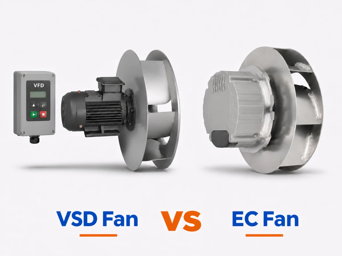
The cube law is why EC fan walls pay back: most ventilation systems spend most of their life below design flow.
4 Steps for a Fan Wall Design
Step 1 — Define the Duty Before Selecting the Fan
Start with the system requirement. Write down how much air is needed and what path it takes:
|
Input |
What to record |
Why it matters |
|---|---|---|
|
Airflow |
Design, minimum, maximum; actual volume at operating temperature or standard flow |
Actual and standard flow differ by the density ratio |
|
Air condition |
Temperature, altitude, humidity, dust |
Sets density and the fan’s temperature rating |
|
Pressure & boundaries |
Required pressure, static or total, and the two locations it is measured between |
The most frequent source of wrong selections |
|
Path |
Every section: size, length, bends, transitions, merges |
Needed for the resistance calculation |
|
Components |
Filters, coils, silencers, louvres, dampers, guards — with pressure-drop data |
Often larger than all the ductwork |
|
Operation |
Fans running together, speed control, what must still work with one fan out |
Decides isolation and redundancy |
|
Space & limits |
Envelope, service access, noise limit, supply voltage |
Limits fan size and number |
Step 2 — Calculate the Pressure Losses Along the Airflow Path
Follow one air path from inlet to outlet and add up what each element costs:
Straight duct: Δp = f × (L/D_h) × p_v. For sheet-metal ducts above ~300 mm, the Darcy friction factor f sits between 0.015 and 0.020. In compact equipment, friction is usually the smallest item; fittings and components dominate.
Bends, openings, merges: Δp = ζ × p_v, with ζ referenced to a stated cross-section.
For the full duct-pressure walkthrough — friction factors, fitting tables, filters and terminals — see our static pressure calculation guide. Here we keep only what changes when the fans run in parallel.
With fixed geometry and turbulent flow, total loss follows Δp = K·Q². One calculated point therefore fixes K — and the whole system curve. Filters that load up and control dampers mean you calculate the clean and the dirty case.
What a velocity costs?
This is the quickest way to judge whether a compact outlet is affordable:
|
Velocity |
Velocity pressure (20 °C) |
Cost of a sharp exit + one plain 90° elbow (ζ ≈ 2.2) |
|---|---|---|
|
4 m/s |
10 Pa |
19 Pa |
|
8 m/s |
38 Pa |
77 Pa |
|
12 m/s |
86 Pa |
172 Pa |
Pressure cost rises with the square of velocity. Going from 8 to 12 m/s more than doubles it.
Two rules that get ignored:
- The shared section carries the sum of the branch flows. Never continue it at the size of one branch.
- Branch losses of different fans are never added together. Each fan overcomes its own branch plus the shared section at total flow.
Step 3 — Combine the Fans in Parallel
Parallel fans add flow at equal pressure. Series fans add pressure at equal flow. Fan walls and multi-fan cabinets are parallel systems.
To build the combined curve:
- Put all fan curves on the same pressure definition, density and speed.
- If a fan has its own branch (guard, damper, short duct), subtract that branch loss from its curve first.
- At each pressure, add the flows of all running fans. Identical fans: multiply by the number running.
- Draw the system curve of the shared section and read the intersection. Our fans in series & parallel calculator does this step for identical fans.
- Divide back to find each fan’s operating point — and check its power, efficiency and noise there.
How much does a second fan actually add?
It depends where the resistance lives. If it is all in the shared section, a second identical fan adds far less than 100%. If each fan has its own path to free air, it adds almost 100%. The steeper the system curve, the smaller the gain.
Stay right of the peak
Left of the pressure peak, a fan has two possible flows for one pressure. Parallel fans there can hunt — one takes the load, the other stalls, then they swap. Select so the duty pressure is no more than about 80% of the highest pressure on the curve at that speed, and re-check at minimum speed with dirty filters.
Different fans in parallel?
Possible, but the weaker fan can be pushed to zero flow — or backwards — whenever system pressure exceeds its own maximum. Use identical fans at identical speed unless there is a strong reason not to.
Step 4 — Give the chamber the dimensions of a housing
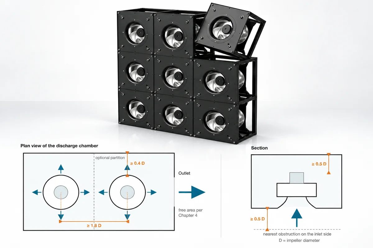
A plug fan has no scroll. Air enters axially through the inlet cone and leaves radially around the whole impeller. The chamber around it does the job of a housing, so its dimensions are part of the fan’s performance.
|
Dimension |
Starting target |
If it is smaller |
|---|---|---|
|
Centre distance between fans |
≥ 1.8 D |
Discharge flows collide — add a partition between the impellers |
|
Impeller rim to wall or partition |
≥ 0.4 D |
Radial flow throttled; pressure and efficiency fall |
|
Motor end to facing wall |
≥ 0.5 D |
Flow cannot turn; motor cooling suffers |
|
Free space upstream of inlet cone |
≥ 0.5 D (1 D preferred) |
Uneven inflow; lower flow, more noise |
|
Elbow upstream of the inlet |
≥ 3 D straight, or turning vanes |
Swirl at the inlet — the largest system effect of all |
For the merge: a chamber cross-flow velocity at or below 4–5 m/s equalises pressure, so each fan sees nearly the same back-pressure. Never merge two streams head-on. Ducted branches join at 45° or less, with similar velocity in both streams.
And note: a partition does not make fans independent. As long as the streams meet again downstream, each fan still feels the other through the shared pressure — and a stopped fan is still a leak path.
A 3+1 fan wall, calculated — not scaled by a ratio
Requirement: 30,000 m³/h at 700 Pa, standard air, resistance in the shared section. Fan: LWBE3G450-188NT-21.
- One fan at 2,800 rpm delivers 11,310 m³/h at 700 Pa. Three fans cover 33,930 m³/h, so N = 3 and four are installed.
- Normal operation, four fans: each 7,500 m³/h at 700 Pa, reached at about 2,140 rpm — 77% of maximum speed. That 70–85% band is the reserve for filters, tolerances and a lost fan.
- One fan out, speed unchanged: the wall drops to 24,820 m³/h — 83% of design, not the 75% a simple ratio suggests.
- One fan out, the other three raised to 2,800 rpm: 32,920 m³/h — 110% of design. N+1 is met, provided the idle fan is isolated and motor power stays within its limit.
Two design rules fall out of this:
- N+1 must be calculated, not ratioed. With one fan out, solve the operating point again with N fans against the system curve. Scaling the rated total by N÷(N+1) is wrong in both directions, because system pressure also changes.
- An idle fan is an open hole. Without a backdraft damper, air returns through the stopped fan and the wall loses far more than one fan’s share. Every module that may stop needs isolation — and its open-position pressure drop belongs in the budget.
|
Topic |
Recommendation |
|---|---|
|
Speed signal |
0–10 V or PWM. Give all fans in one group the same signal; do not run identical parallel fans at different speeds. |
|
Control on |
Duct or chamber static pressure for variable systems; fixed setpoint for constant ones. |
|
Feedback |
Monitor speed or alarm output of every fan — a stalled fan may still report a signal. |
|
Minimum speed |
A floor above the unstable region and above the speed where backdraft dampers close. |
|
Staging |
Prefer all fans at reduced speed to some at full speed: P ∝ n³ makes it more efficient and keeps flow even. |
|
Fault sequence |
Detect → isolate the failed fan → raise the others → alarm. Test this sequence; do not only write it. |
The Worked Example Behind the Method
The full guide runs this same method end-to-end on a two-fan cabinet exhaust: 7,646 m³/h per fan at 872 Pa and 50 °C, through catalogue correction (960 Pa), outlet sizing (900 × 600 mm free area at 7.9 m/s), a 928 Pa path budget, a parallel stability check (duty at 66% of peak pressure — well right of the peak), and a sharing check that shows a 10 Pa path difference shifts only about 60 m³/h per fan.
It also covers the three layout options for that cabinet and ends with copyable worksheets: a design record, a per-path pressure budget, and a release checklist.
Need help applying this to your equipment? Send us the design record — airflow, pressure and its two reference points, air condition, and the dimensioned path — and our engineers will return the operating point, speed, input power and a layout review: LONGWELL fan wall solutions.
FAQs
Does running two fans in parallel double the airflow?
No. Parallel fans add flow at equal pressure, and the gain depends on the system curve. If resistance is concentrated in the shared section, the second fan adds far less than 100%. In the worked example, one fan out with the other three boosted still delivered 110% of design — but one fan alone reached only 61–76%.
What is N+1 redundancy in a fan wall?
With any one fan out, the remaining N fans still deliver the required flow against the system curve, within their speed and power limits. We cover the counting logic — turndown, cost, maintenance — in how many fans a fan wall needs; the part most explanations skip is that it must be found by solving the operating point with N fans, not by scaling the rated total by N÷(N+1).
How far apart should plug fans be in a fan wall?
Start at a centre distance of 1.8 impeller diameters (1.8 D), with 0.4 D from impeller rim to wall and 0.5 D of free space at the motor end and upstream of the inlet cone. Confirm against the installation drawing of the selected fan.
Can fans of different sizes or speeds run in parallel?
They can, but the weaker fan can be pushed to zero flow or backwards whenever system pressure exceeds its own maximum. Use identical fans at identical speed unless there is a strong reason not to.
What speed should a fan wall normally run at?
Select so normal operation is at 70–85% of maximum speed. That is the reserve for filter loading, manufacturing tolerances and a lost fan.
Why does my fan deliver less than its catalogue airflow?
The catalogue figure is the free-blowing end of the curve at zero pressure. The system runs where the fan curve crosses the system curve — and nearby elbows, walls and obstructions (system effect) reduce it further. AMCA Publication 201 covers this in detail.
Worked examples use LONGWELL test data for LWBE3G450-188NT-21 (standard air, straight lines between published points). They are engineering estimates, not a performance guarantee; final performance is confirmed by measurement. Typical values are starting points for a first design — replace them with component data before a design is released. Explosion-protected, smoke-extract, corrosive-gas and life-safety systems need their own product approvals and design review.