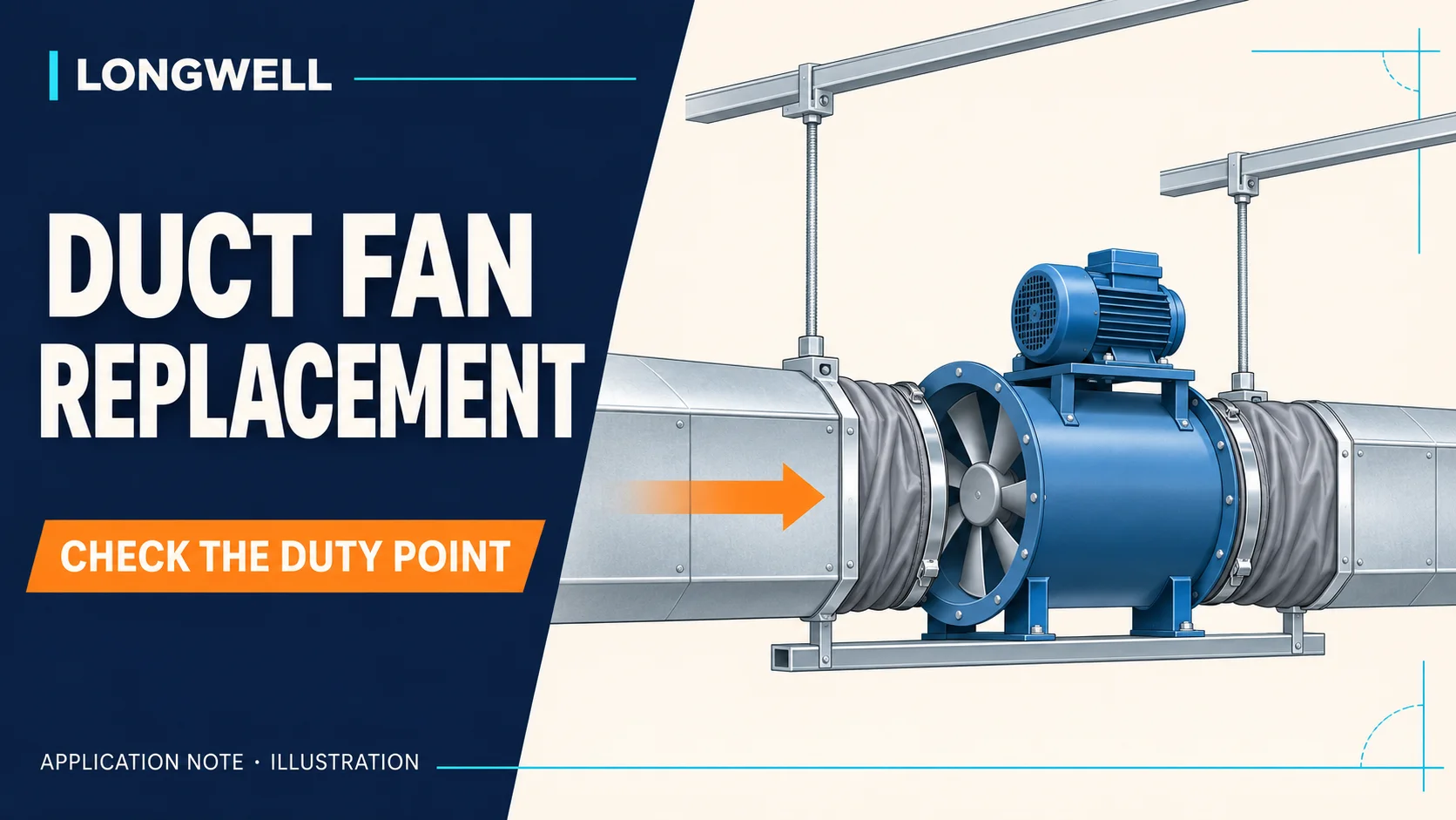
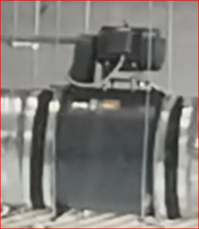
An industrial exhaust project in Jordan needed to replace two external-motor tube axial fans installed in suspended duct sections. Flexible connectors joined the fans to the ductwork. The customer wanted to retain as much of that arrangement as possible while increasing airflow.
The enquiry mentioned approximately 34,000m³/h at 500Pa, a 380V three-phase supply and a preferred power range of 4–5kW. Before confirming a model, the assessment needed two answers: was the airflow requirement per fan or for the system, and what pressure definition applied to the target?
Turn the nameplate and installation into separate requirements
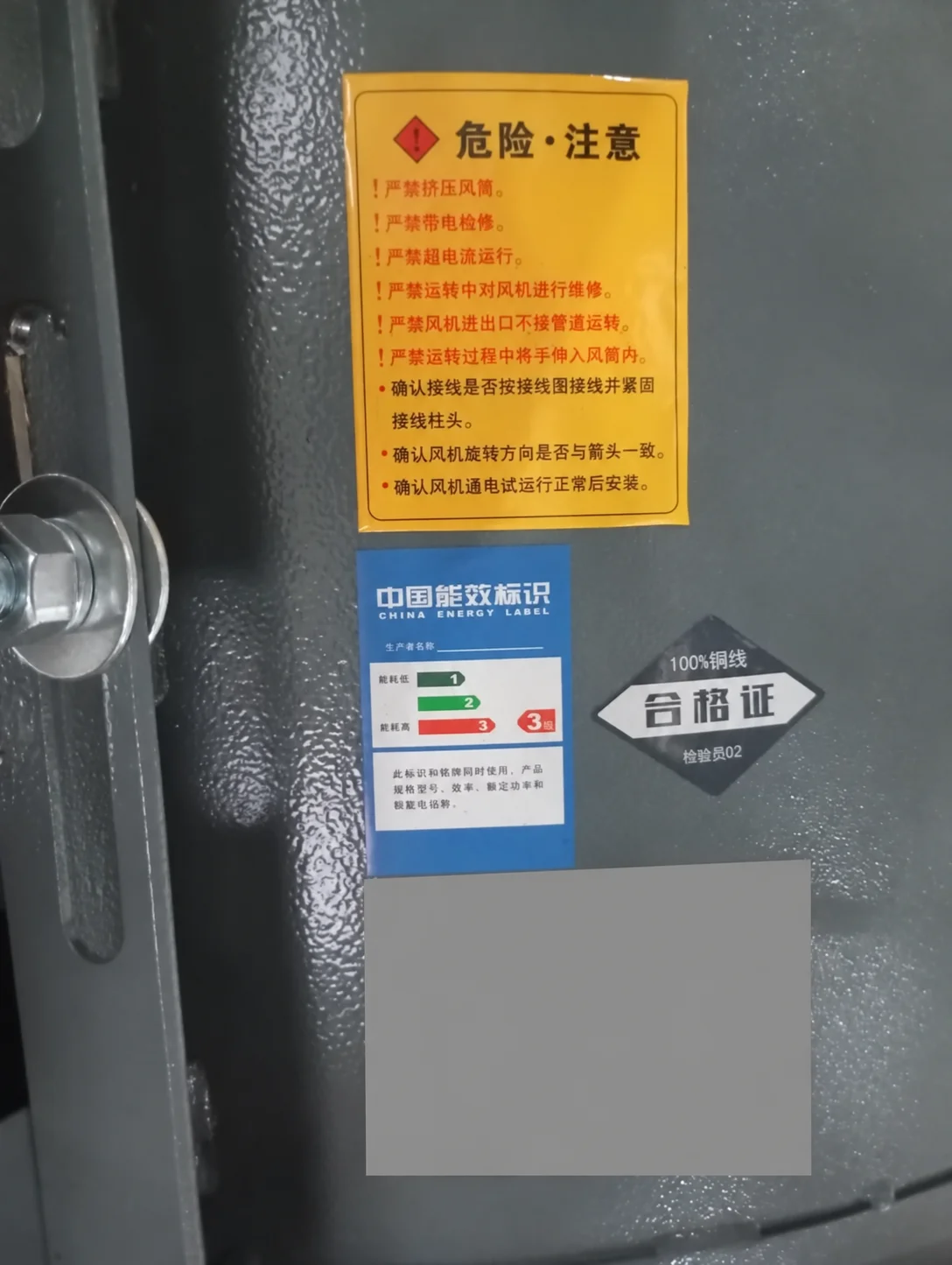
The original nameplate reference included 32,000m³/h, 500Pa total pressure, 4kW, 380V and approximately 2,900rpm, with a size No. 6 designation. Those figures provide a comparison reference. They are not a measurement of current airflow in the installed duct system.
The size designation also does not define the flange pattern, casing length or support arrangement. A replacement review needs the mechanical details alongside the aerodynamic requirement.
Keep 500Pa total pressure distinct from static pressure
Fan total pressure and fan static pressure are different quantities. AMCA’s explanation of fan curves describes total pressure as including static pressure and velocity pressure. A 500Pa total-pressure requirement cannot simply be relabelled as 500Pa static pressure.
The new target needs a confirmed pressure basis and supporting design or measurement information. Without the relevant outlet area and operating data, assigning a converted static-pressure number would add an unsupported assumption.
Reject a capacity shortfall before refining the mounting
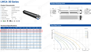
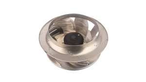
Similar construction does not establish sufficient airflow. As a screening comparison, the public LWMFAF630-01 listing gives a maximum airflow of 15,000m³/h, while LWEA630TM-167E is listed at 18,250m³/h maximum. If 34,000m³/h is required from each fan, neither is a valid selection for that airflow. A higher-capacity solution needs investigation.
If the number refers to system total flow, adding two catalogue maxima still does not confirm the duty. The review must establish which branches the fans serve, whether they share ductwork and the resistance each fan encounters. Their installed operating points, rather than free-air maxima, determine the resulting flow.
The preferred 4–5kW power band also remains a customer constraint to assess. It is not evidence that a specific motor and fan combination can deliver the target duty.
Measure the interfaces that must remain
| Site information | Purpose |
|---|---|
| Flanges, hole centres and clear connection diameter | Check the existing flexible connectors |
| Casing length and space above the motor | Assess installation and maintenance access |
| Suspension points and support structure | Review replacement weight and support requirements |
| Duct layout for both fans | Separate per-fan and total-system duties |
| Supply, frequency and connections | Confirm the motor and control configuration |
An airflow increase also calls for checking the existing duct and connector arrangement. Retaining the current installation is a project objective, with feasibility still dependent on the final configuration.
Confirm the duty before issuing a replacement model
A useful starting package includes the nameplate, measured installation photographs and a sketch showing how the two fans connect to the system. Add the original curve, duct design or field readings where available. Label each reading with its measurement location and operating condition. Also identify whether both fans operate together, serve separate equipment or follow another operating sequence. These details prevent a system-level target from being assigned to the wrong fan and give the engineering review a consistent basis for comparison.
Once the per-fan flow, pressure basis and interfaces are clear, candidate curves can be compared on consistent terms. The motor, casing and mounting arrangement can then be reviewed together. Where performance and space constraints conflict, the discussion may require a larger size, another construction or duct changes.
Choose the right axial fan
Longwell manufactures 1,048 axial fans in-house. Send airflow, static pressure and voltage — an engineer replies with a matching model, performance curve and price within one working day.