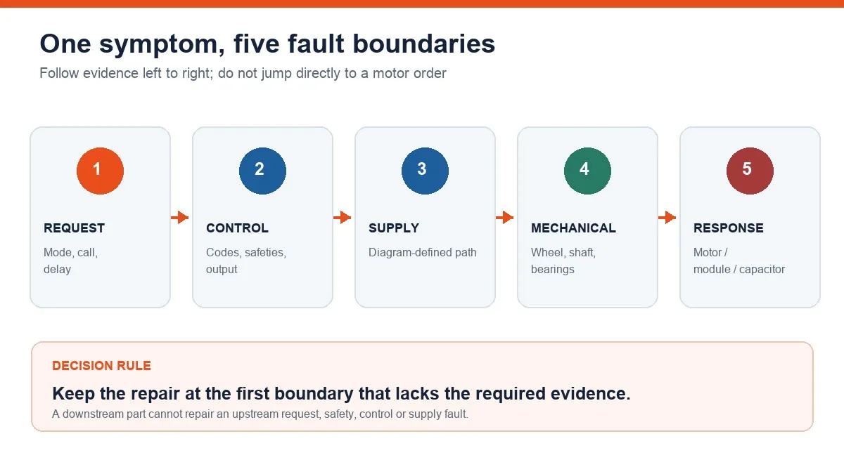
A furnace blower that does not turn has one symptom, but several possible fault boundaries. The motor may never have received a valid request, a safety or control may have interrupted the sequence, the wheel may be mechanically blocked, or the motor-specific supply and command may be present without a response. Diagnose those boundaries in order before selecting a replacement.
Homeowners can record thermostat settings, visible fault indicators, timing, sound, odor, filter condition, and whether the blower ever attempts to start. Opening the cabinet, handling stored energy, or making electrical measurements belongs to qualified personnel following the exact furnace manual and the site energy-control procedure.
Freeze the evidence before resetting anything
Write down the equipment model, thermostat mode, requested operation, and the complete sequence observed. Note whether the furnace is silent, whether another component starts, whether the blower hums or moves briefly, and whether the symptom appears in fan-only, heating, cooling, or every mode. Photograph any displayed or flashing code before power is cycled.
Stop immediately for smoke, scorching, gas odor, a carbon-monoxide alarm, unusual cabinet heat, or damaged wiring. Leave the hazard area and follow the equipment manufacturer, utility, or emergency guidance as applicable. A reset can erase useful evidence and can also restart equipment automatically; it is not a diagnostic result.
Establish the service safety boundary
A thermostat switch, control-board button, or blower-door interlock is not an energy-isolating device. Before access, qualified service personnel must identify every relevant source, de-energize under the prescribed procedure, apply the required lock or tag controls, control stored energy, and verify the condition with appropriate test equipment. Furnace work can also involve rotating and combustion hazards.
Do not bypass a door switch, interlock, fuse, ground, limit, or protector to make the blower run. Do not assume a stopped wheel is safe to touch. The furnace instructions and site procedure control access, temporary testing, restoration of guards, and re-energization.
Step 1: confirm that a blower request exists
Begin at the intended operating sequence, not at the motor terminals. Compare the thermostat request and configured mode with the furnace documentation. Record any manufacturer-defined delay and the exact point where the observed sequence diverges. If there is no valid request, the decision remains in thermostat settings, field wiring, configuration, or an upstream sequence—not in motor replacement.
A fan-only request can be useful evidence, but it is not a universal proof. Different modes may use different programmed outputs or motor commands. Diagnose every relevant mode from the exact wiring diagram rather than transferring a terminal name, conductor color, or expected delay from another furnace.
Step 2: read controls, safeties, and airflow clues
Preserve the fault code and use only its model-specific definition. Qualified service should then trace the request through the applicable safety and control sequence. A panel state, open protective device, damaged connector, absent control output, or interrupted supply path can all leave a healthy motor stationary.
Record the filter and return-air condition without treating restriction as proof of a motor fault. A loaded air path, high static pressure, repeated protection event, or abnormal temperature may explain intermittent operation or overheating, but the finding must be confirmed against the equipment procedure. “No spin” and “spins but moves no air” are different diagnoses.
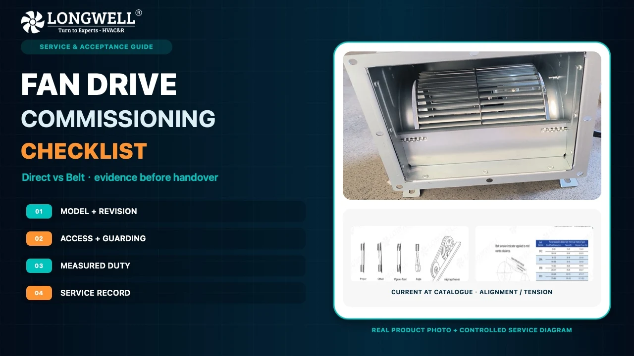
Step 3: inspect the de-energized mechanical path
After isolation has been verified and the manufacturer permits access, inspect for an obstruction, damaged wheel or hub, rubbing, shaft displacement, bearing drag, contamination, and loose mounting. Do not force or power-spin the wheel. A blocked wheel can prevent a good motor from starting, while a freely moving wheel only clears one branch of the fault tree.
Keep the circulating-air blower separate from the combustion inducer. They serve different furnace functions and have different diagnostic paths. If cleaning is the next confirmed action, use the furnace-specific method; do not disturb balance clips, alignment, wiring, or the motor while improvising a generic cleaning procedure.
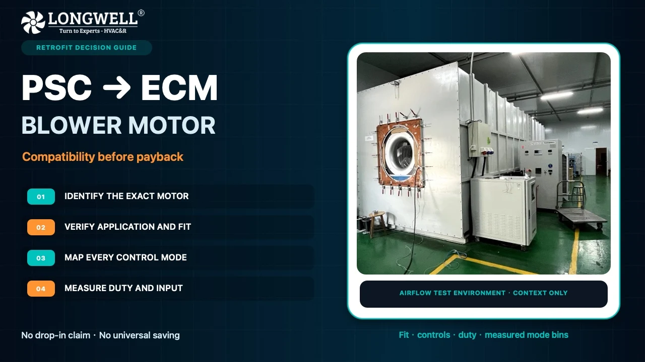
Step 4: identify PSC or electronic-control architecture
The motor label, furnace model, connector, and unit wiring diagram must agree before testing begins. A PSC architecture may use a separate run capacitor and selected speed leads. Longwell’s AC fan motor overview provides general construction context only; it is not a furnace wiring or service authority. An electronically controlled motor can require line power, a distinct enable or speed request, an electronic module, and model-specific service information. Similar housings do not make those interfaces interchangeable.
Longwell’s EC motor overview explains electronic commutation at a product-technology level. It does not provide a furnace pinout, programming profile, replacement equivalence, or authorization to test energized equipment. Use the exact OEM diagram for every conductor and test point.
Step 5: let qualified measurements split the fault
Measurements should answer a sequence of bounded questions: Is the expected control request present? Does the control produce the specified output? Does the motor receive the model-defined supply and command under that condition? Does it respond as the manual requires? The technician selects rated instruments, access points, test order, and acceptance values from the exact documentation.
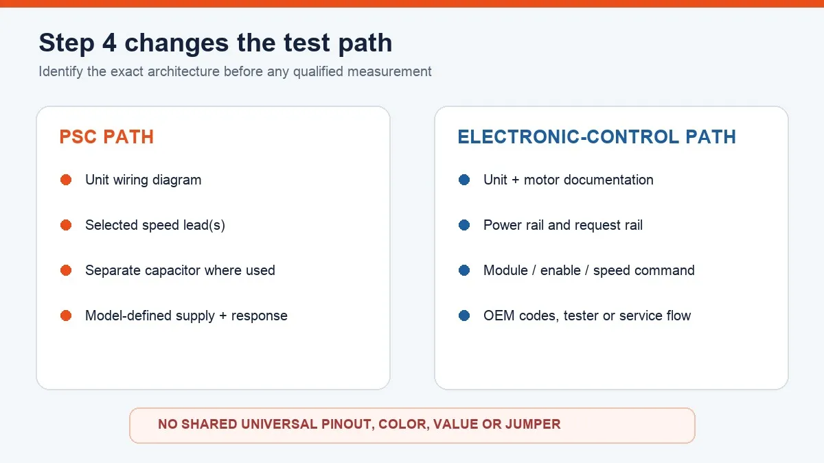
A PSC capacitor is evaluated only under the equipment and component procedure; an electronic module follows its own diagnostic flow. This article intentionally gives no universal voltage, resistance, capacitance, discharge time, jumper, wire color, or fault-code value. A correct reading at one boundary does not prove every downstream connection or load is sound.
Map the result, repair once, and commission the system
No request keeps the repair upstream. A valid request without the required control output keeps it in the control or safety chain. Correct control output without motor supply points to the power path or connection. Correct model-specific supply and command with a free mechanical path narrows the decision to the capacitor where used, connector, module, motor, or integrated assembly under the OEM flowchart.
Do not order from horsepower, diameter, voltage, or connector appearance alone. Capture the furnace model, motor label, mechanical envelope, wheel relationship, rotation, supply, control interface, speed profile, mounting, and OEM programming requirements. A broad fan-motor range is a sourcing overview only; it cannot establish furnace compatibility without the complete interface record.
After the confirmed repair, restore every connector, ground, guard, panel, interlock, and wire support. Commission all requested modes under the furnace procedure. Verify starting, rotation, speed response, fault status, current where required, airflow, temperature rise where specified, vibration, sound, and safe shutdown. The job is complete only when the furnace delivers the required airflow without returning the fault.
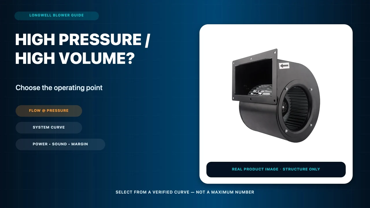
Choose the right blower
Longwell manufactures 247 blowers in-house. Send airflow, static pressure and voltage — an engineer replies with a matching model, performance curve and price within one working day.