A noisy blower motor does not automatically need new bearings or a new motor. Similar sounds can come from wheel imbalance, looseness, rubbing, airflow restriction, a belt or sheave, vibration isolators, electrical tones, or the structure surrounding the blower. Sound is an alert, not a diagnosis.
A defensible fix-or-replace decision connects the symptom to speed, vibration, temperature, shaft condition, mounting, and the exact motor construction. Blowers also contain hazardous electrical energy, stored energy, and rotating parts. Contact inspection requires verified isolation and zero speed; energized testing and internal motor work belong to qualified personnel following the equipment and motor manuals.
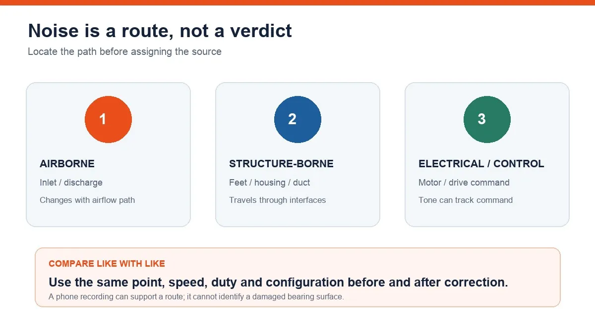
Separate airborne, structure-borne, and electrical sound
Airborne noise travels through the inlet and discharge. Structure-borne vibration moves through motor feet, housing, ductwork, or the appliance cabinet. Electrical and control tones may vary with line frequency, electronic commutation, or speed command. Record where the sound is strongest and how it changes from startup to steady load.
Capture the operating mode, commanded and measured speed, airflow restriction, cabinet condition, temperature, and load. Never place a hand, screwdriver, loose microphone, or improvised probe near an exposed rotating component. A recording is useful only when its measurement location and operating condition are known.
Rule out look-alike faults under the same duty
Check for debris, wheel-to-housing contact, loose mounts, damaged isolators, an unbalanced or damaged wheel, belt and sheave problems where fitted, obstructed airflow, and control-related tones. Correct external causes before opening the motor or condemning a bearing.
Compare sound and vibration at the same point, speed, duty, filter condition, and cabinet configuration. A before-and-after recording made at different speeds or with an access panel removed is not a clean comparison.
A stable once-per-revolution component may support an imbalance hypothesis, while multiple running-speed harmonics or repetitive impacts may support looseness or contact. Rolling-bearing defects can generate higher-frequency impacts, but theoretical defect frequencies depend on bearing geometry, speed, contact angle, and slip. A phone spectrum alone cannot prove which bearing surface is damaged.
Inspect only after verified energy isolation
Stop the blower, physically isolate every applicable energy source, apply the required lockout and tagout procedure, control stored energy, wait for zero speed, and verify de-energization. A wall switch, software stop, or speed command is not an energy-isolating device.
With the machine safely isolated, rotate the shaft only where the manufacturer permits and with the proper method. Inspect for roughness, binding, specified radial or axial play, heat discoloration, seal damage, lubricant leakage, contamination, loose bearing fit, shaft wear, and contact marks. Compare temperatures under equivalent load rather than relying on one isolated hot reading.
The visible LONGWELL factory bearing-assembly operation provides process and scale context only. It does not depict a noisy field bearing, prove a diagnosis, or demonstrate a universal repair or lubrication method.
Choose correction, lubrication, rebuild, or replacement
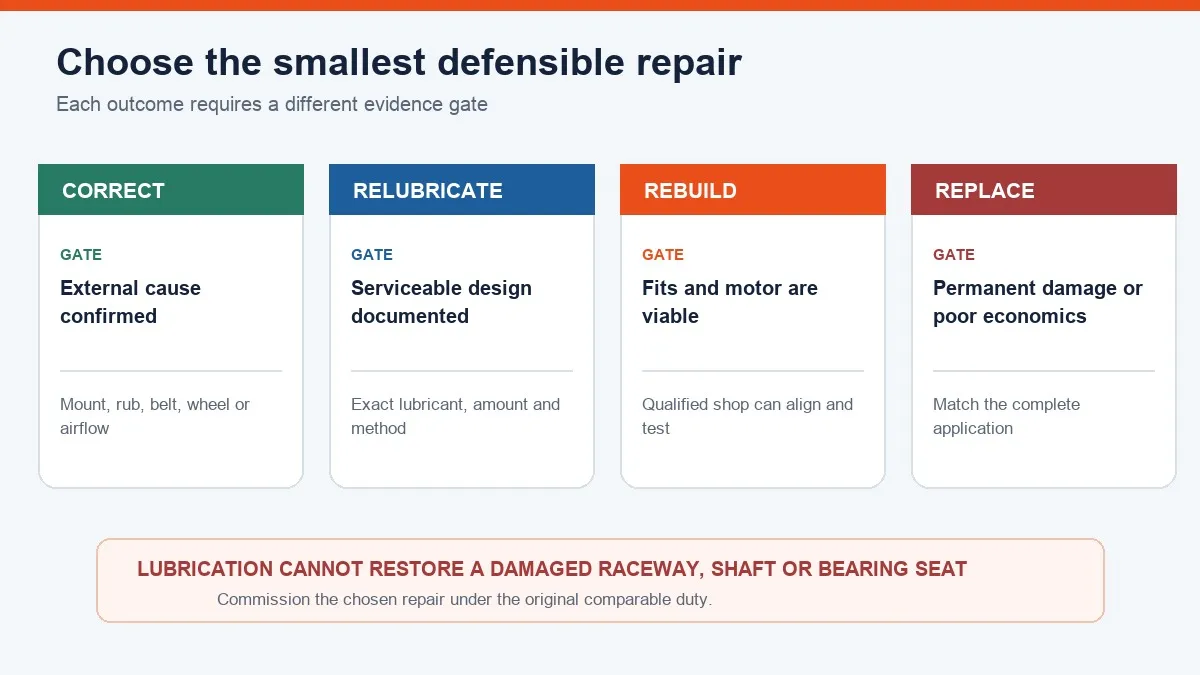
Correct the external cause when evidence points to rubbing, mounting looseness, isolation failure, restricted airflow, belt condition, or wheel imbalance. Relubricate only when the motor has a documented serviceable bearing and the exact manufacturer procedure specifies the lubricant, amount, interval, fitting, and purge method.
Do not spray general-purpose lubricant into a sealed motor. Mixing incompatible greases, contaminating a fitting, or overgreasing can increase temperature and damage. Lubrication cannot restore a damaged raceway, worn fit, bent shaft, or other permanent defect.
Consider a qualified rebuild only when the motor design is serviceable, shaft and bearing seats are sound, windings and controls pass inspection, and a capable shop can install, align, balance, and test the assembly. Replace the motor or blower module when bearings are inaccessible, fits are damaged, overheating or corrosion is extensive, integrated electronics have failed, or verified rebuild cost, downtime, and application criticality favor a warranted assembly.
Motor architecture changes the service boundary. Longwell’s AC fan motor overview and EC motor overview provide general technology context only; neither establishes bearing serviceability, lubrication instructions, wiring, programming, or replacement compatibility for a particular blower.
Recommission and compare on the original condition
After the approved repair, restore guards, fasteners, wiring protection, and isolation components. Conduct a controlled commissioning test and record speed, current, airflow or pressure, vibration at the same locations, sound, and temperature trend. Verify every commanded mode.
Confirm that the original symptom is gone without introducing rubbing, resonance, overheating, or lost airflow. A quieter recording alone does not prove a successful repair if the operating point changed or fan performance declined.
The service record should include the motor plate, operating duty and speed, sound and vibration files with measurement locations, temperature trend, shaft and mounting findings, root cause, repair scope, and recommissioning results. That evidence supports a repair-or-replace decision without treating noise as a verdict.
Choose the right motors & drive system
Longwell manufactures 37 motors & drive systems in-house. Send airflow, static pressure and voltage — an engineer replies with a matching model, performance curve and price within one working day.