Variable speed can reduce fan energy when the required duty falls, but a lower speed command is not a savings certificate. The result depends on the real load profile, the system curve, the control objective, the usable speed range, and the electrical input of the complete fan-motor-control package.
A defensible decision therefore starts with operating evidence, not a universal percentage. Define when less airflow or pressure is genuinely acceptable, compare the existing and proposed systems at matched duty points, and verify the final sequence in the installed equipment.
Record the Duty Profile Before Choosing a Control Method
“Part load” should describe measured or specified operating states. Divide the year into useful load bins: design demand, typical occupied or production demand, low demand, standby, and off. For each bin, record required airflow, pressure, hours, process constraints, and the control state of dampers, bypasses, or cycling fans.
Keep the baseline explicit. A fixed-speed fan throttled by a damper is different from one that already stages off, and a process fan with a minimum transport velocity is different from a comfort-ventilation fan. Variable speed only has an opportunity where demand can fall without violating ventilation, cooling, capture, safety, or product-quality requirements.
Use the Fan Laws as a Screening Tool, Not a Meter Reading
For the same fan under dynamically similar conditions, airflow changes approximately with speed, pressure with speed squared, and shaft power with speed cubed. Those relationships explain why speed reduction can be attractive. They do not predict annual electrical savings by themselves.
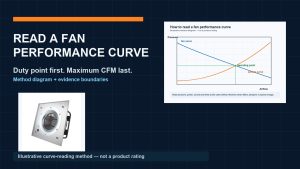
The estimate changes when air density, geometry, filters, dampers, controls, motor efficiency, drive losses, or the operating point changes. Start by finding the fan curve and system curve intersection at each proposed speed. This fan-curve operating-point guide helps keep airflow, pressure type, speed, and power on the same boundary; its examples are not a guarantee for another fan or installation.
Check the System Curve and the Control Objective
A speed controller needs a trustworthy reason to change speed. That reason might be measured airflow, temperature, differential pressure, process demand, or another project-specific variable. Define the sensor location, setpoint logic, response time, alarm behavior, and which controller has final authority.
Then review how the installed air path moves the operating point. Closing terminals, dirty filters, coil conditions, duct changes, and parallel fans can all alter resistance. A controller that holds an unnecessarily high fixed-pressure setpoint may leave much of the opportunity unused. A reset strategy can be considered only after downstream minimums and stability are protected.
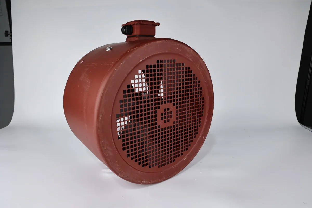
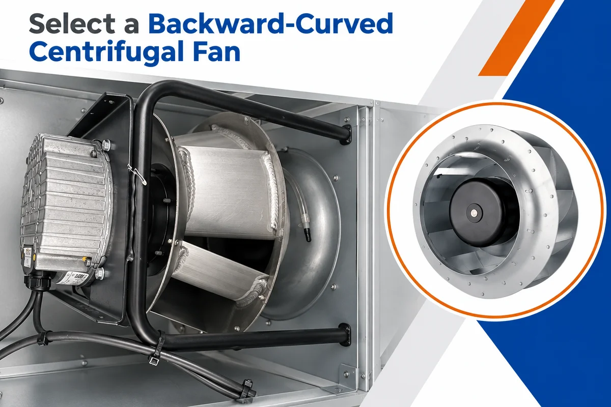
The photograph shows an enclosed fan housing and inlet guard only. It does not establish a control method, motor type, curve, efficiency, minimum speed, installed result, certification, or suitability for a particular duty.
Define a Usable Speed Envelope
Do not assume that every command between zero and full speed is acceptable. Obtain the fan, motor, drive, and controller limits for the exact combination. Review motor cooling, current, drive switching and cable requirements, critical or excluded speed bands, aerodynamic stability, bearing and lubrication instructions, noise, and the minimum airflow required by the process or equipment.
Document a minimum operating speed, any prohibited bands, acceleration and deceleration behavior, restart conditions, and fault response. These limits are application-specific. They should come from controlled manufacturer documentation and commissioning evidence rather than a generic rule copied from another installation.
Compare the Complete Fan, Motor, and Control Package
An AC motor with a compatible variable-frequency drive and an electronically commutated fan can both provide variable operation, but their interfaces and loss boundaries differ. Compare complete electrical input at the same airflow and pressure, along with control compatibility, harmonics or electromagnetic requirements, thermal limits, redundancy, service access, and the project acceptance plan.
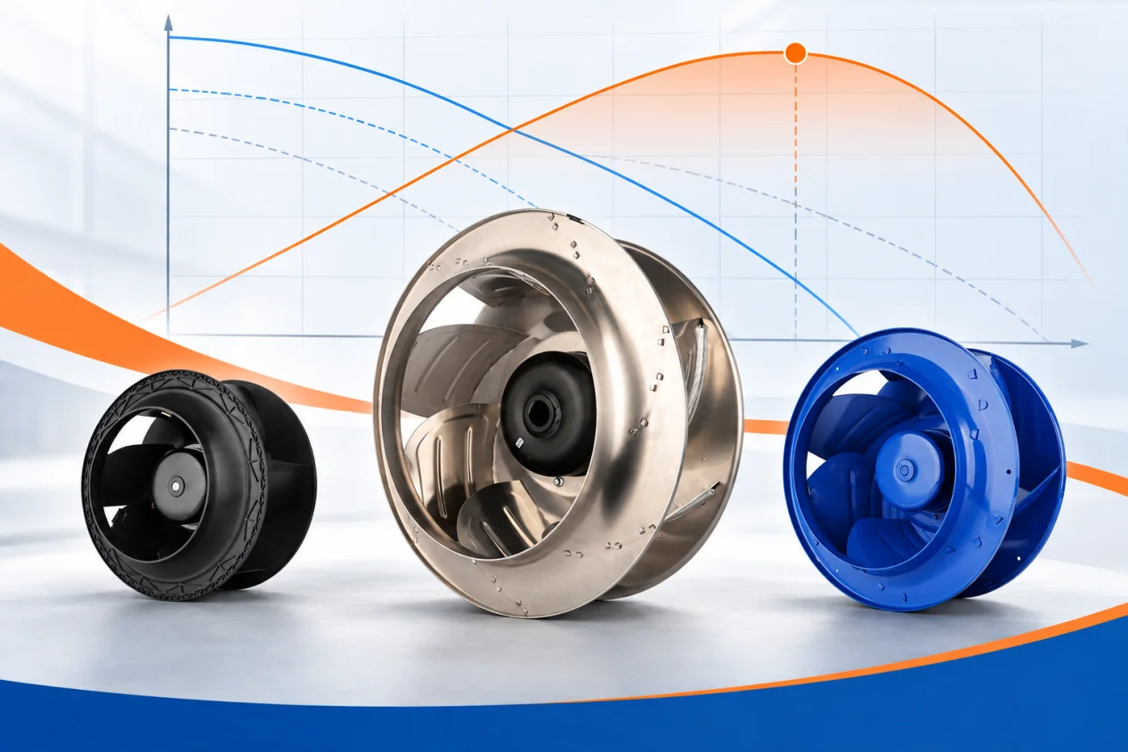
The EC plug-fan family entry point is a product-family discovery route, not an exact selection. Its page and the images here prove no energy result, compatibility, certification, replacement equivalence, or project suitability.
Build the Energy Case from Load Bins
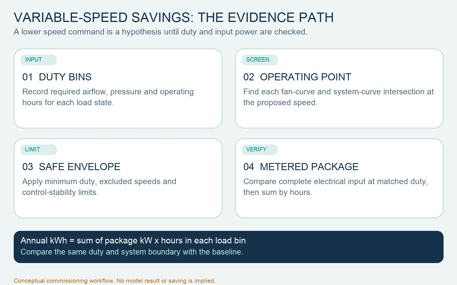
For each operating bin, use measured input power or a traceable estimate at the required duty, multiply by the hours in that bin, and sum the results. Apply the same boundary to the baseline and proposal. Include drives, controls, auxiliary cooling, standby consumption, parallel-unit staging, and any equipment that changes because of the control strategy.
Keep electricity price, demand charges, maintenance assumptions, and operating growth separate so reviewers can change them without rebuilding the technical model. The AC-to-EC ROI boundary guide is useful calculation context, but no linked example is evidence of savings or payback for this project.
Commission and Verify at Representative States
Commission the system at design, typical, and low-load conditions. Record airflow, relevant pressure, speed, complete electrical input, sensor values, commanded state, damper or valve position, and alarms using suitable instruments. Confirm that required service is maintained and that the system does not hunt, enter a prohibited band, or mask a developing restriction.
Trend the same variables after handover. Compare actual hours and power by load bin with the approved baseline, and investigate material differences before reporting savings. The credible conclusion is not “variable speed always saves energy.” It is that this defined control sequence, inside this verified operating envelope, reduced measured input while still meeting the required duty.