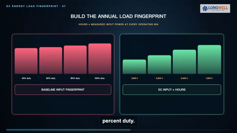
Short answer: size a fan wall from the one-fan-unavailable condition, not from the number of openings that fit the cabinet. First find how many healthy fans can deliver the required airflow at the required pressure using dependable installed performance. Then add the declared redundancy and prove the result with the actual array configuration.
For a simple N+1 requirement, use this screening sequence: operating fans = ceiling(required airflow ÷ dependable per-fan airflow at the same pressure); installed fans = operating fans + 1. The arithmetic is only the first gate. Array curves, air density, speed and power limits, failed-bay isolation, shared controls, cabinet geometry, sound, and the acceptance test still decide whether the count is usable.
Write the N+1 promise before counting fans
“N+1” should answer a precise question: how many fan modules may be unavailable, and what duty must the remaining wall maintain? One unavailable fan is different from one fan under planned service while another fails. It also does not cover loss of a shared breaker, controller, sensor, communication link, or upstream power source unless those common components have their own availability design.
Record the required airflow, pressure type, air condition, operating modes, and failure boundary. State whether all available fans normally share the load or one module waits as a standby. A modular-layout reference can help the discussion, but the project schedule must define the actual redundancy promise.
Calculate at one pressure and with dependable capacity
Fans in parallel add airflow at a common pressure. Do not divide the total airflow by a free-air maximum, and do not add individual fan pressures together. Read the candidate fan or array curve at the project pressure, with the correct air density, speed limit, appurtenances, and test boundary. If the value comes from a single-fan curve, account for the installed array and system effects before calling it dependable.
The fan curve guide explains how to keep airflow, pressure, speed, power, and the curve revision aligned. The result you need here is not “maximum airflow”; it is the capacity one healthy module can be trusted to deliver at the stated pressure in the intended wall.
Worked example: why seven fans can become eight
Take an illustrative AHU duty of 60,000 m³/h at 800 Pa fan static pressure. Assume one candidate fan can dependably provide 10,000 m³/h at that same condition. The first calculation is ceiling(60,000 ÷ 10,000) = 6 operating fans. Add one for the declared N+1 case, giving 7 installed fans.
Check both states. With all seven available and sharing equally, each carries about 8,571 m³/h. After one becomes unavailable, the six survivors must each reach 10,000 m³/h. That failed-fan point—not the comfortable normal point—is the critical curve, speed, input-power, current, stability, and sound check.
Now suppose the dependable installed value is only 9,200 m³/h per fan. Six survivors provide 55,200 m³/h, so seven installed fans fail the stated duty. Recalculate: ceiling(60,000 ÷ 9,200) = 7 operating fans, then add one. The revised N+1 wall has 8 installed fans. These numbers teach the method; they are not ratings for the equipment pictured here.
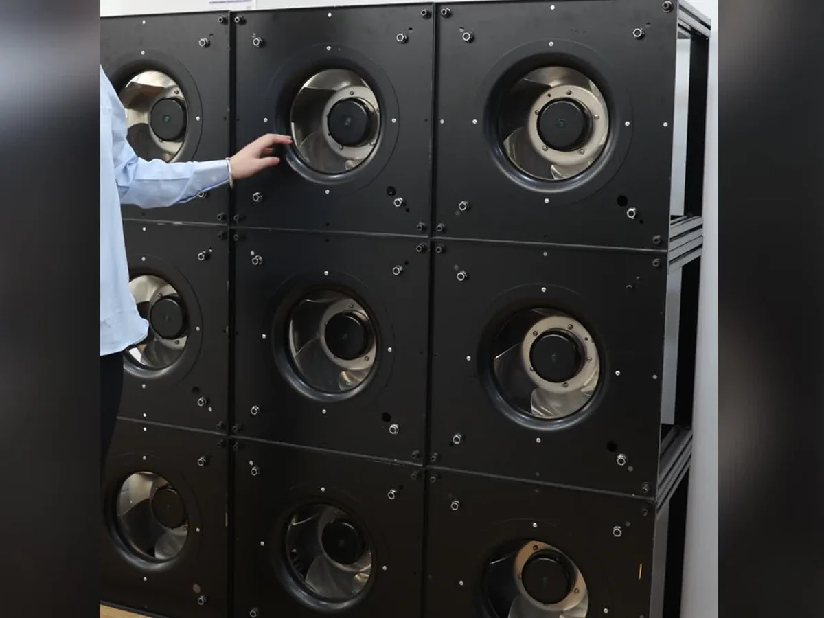
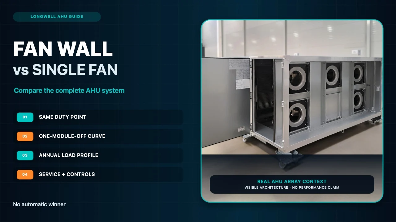
The real 3×3 Longwell assembly above shows the physical form of a modular wall. It does not prove that nine modules suit a particular airflow or pressure. Quantity follows the qualified duty and failure calculation; the grid then has to fit the cabinet and service plan.
Include the failed bay and shared infrastructure
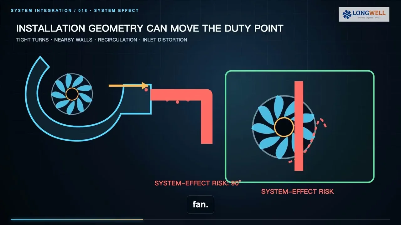
A stopped fan can become a reverse-flow or leakage path. Check the exact backflow or isolation device, its leakage, opening behavior, pressure drop, controls, and safe service position. Partitions and appurtenances can change array performance, so they belong in the tested or otherwise qualified configuration—not as an afterthought.
Next audit common modes. Map power feeds, protection, control groups, pressure or airflow sensors, communications, alarms, and any required fallback. An extra wheel cannot compensate for a shared component that disables the complete wall. Decide which faults the design must tolerate and which faults are simply reported and shut down safely.

The pictured LWBE3G630-188PT-04 is a real Longwell EC plug-fan variant from the authorized product library. It provides visible product and mounting context only. Its model, curve, controller, and revision must not be substituted for the illustrative 60,000 m³/h calculation. Browse the EC plug-fan family only after the project duty and interface are defined.
Fit the answer into a maintainable cabinet
Turn the numerical result into a layout: wall width and height, module spacing, inlet and discharge clearance, access side, removal path, lifting provision, guards, cable routing, isolation-device depth, and controller location. Confirm that technicians can identify and isolate one module without creating an unsafe opening or disturbing unrelated equipment.
Also compare the normal and failed-fan states for speed, electrical input, current, sound, and operating stability. If one state exceeds a documented limit, change the fan, quantity, geometry, or system requirement. Do not rescue an invalid count with a generic speed-headroom percentage.
Commission the one-fan-unavailable state
Before handover, agree on the measurement boundary and acceptance method. Establish the normal operating point, command or safely simulate one unavailable module, verify the isolation response and alarm, then measure total airflow and pressure after the remaining fans settle. Check speed and electrical limits and investigate unexpected vibration, resonance, or uneven flow.
The final selection record should list duty, pressure definition, air density, exact fan and array curve revision, installed quantity, unavailable-fan count, normal and failed-fan points, maximum permitted speed and input, isolation method, common-mode architecture, grid geometry, service clearance, sound target, alarms, and test plan. That record gives buyers, AHU designers, controls teams, and commissioning engineers the same decision trail.