EV charger nameplate power is not the heat load that a cabinet fan must remove. Start with the losses that actually become heat inside the enclosure: power modules, busbars, connectors, control electronics and auxiliary equipment. Those losses can move with charger output, input conditions and component tolerance, so use measured data or a validated loss model across the intended operating range.
The practical question is not “How much free-air airflow can this fan deliver?” It is “Can the complete cabinet keep every protected component inside its limit when the air path, filter, environment and controls are in their credible states?” This guide turns that question into a repeatable selection and validation workflow.
Build the Cabinet Heat Budget First
Separate rated charging output from internal heat loss. List each meaningful heat source and define the electrical state that produces it. Include conversion losses, distribution losses and auxiliary loads, but do not invent a fixed efficiency or assume one nominal point represents the complete duty cycle.
A first-pass energy balance can translate total heat and an allowed air-temperature rise into an estimated airflow. Use that number to size the problem, not to release a fan. Air density changes with temperature and altitude, heat is not evenly distributed, and a local power device can reach its limit before the average exhaust temperature looks concerning. Keep component limits and hotspot locations attached to the calculation.
Select at the Installed Operating Point
Filters, louvers, heat-sink fins, cable bundles, partitions, ducts and outlet grilles all consume pressure. The working point is where the fan curve intersects the cabinet system curve. A catalogue maximum-flow value describes a different boundary and cannot prove installed airflow.
Define at least clean and loaded resistance states, then compare candidates at the same supply, air density, control command and acoustic boundary. The fan-curve operating-point guide explains how to keep pressure, airflow, power and the system intersection on one measurement boundary.
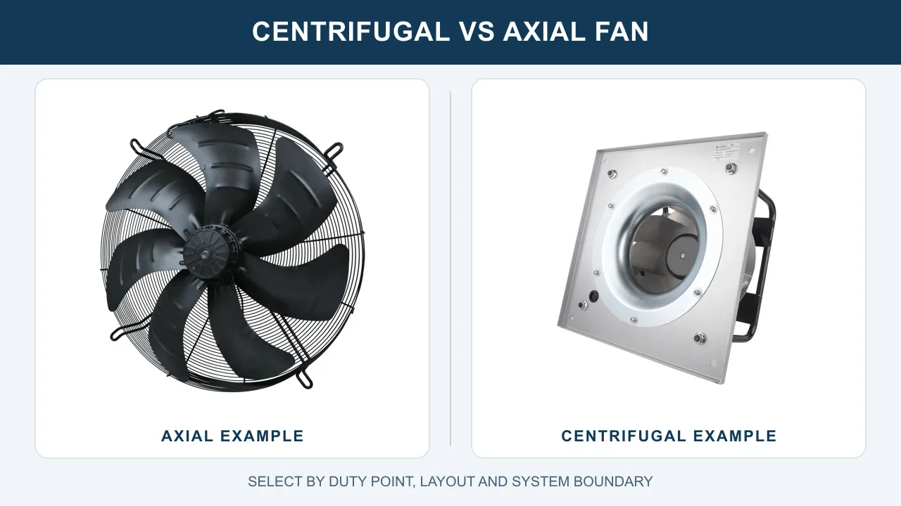
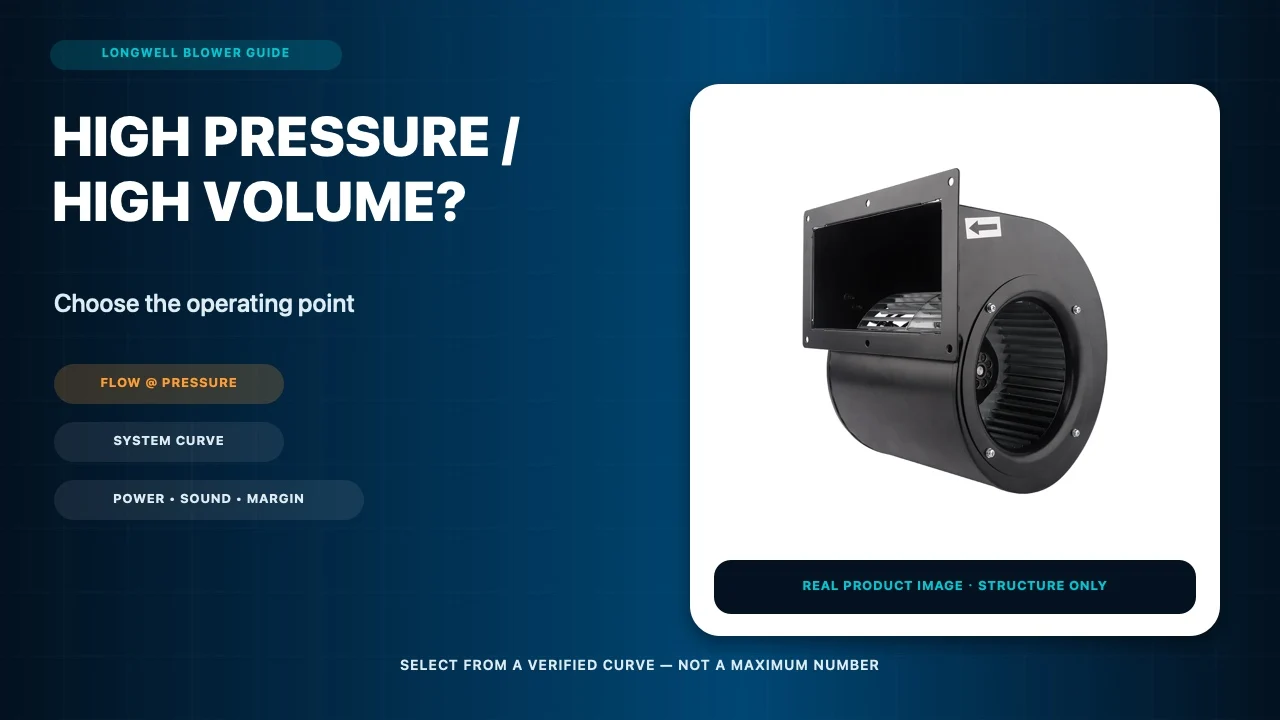
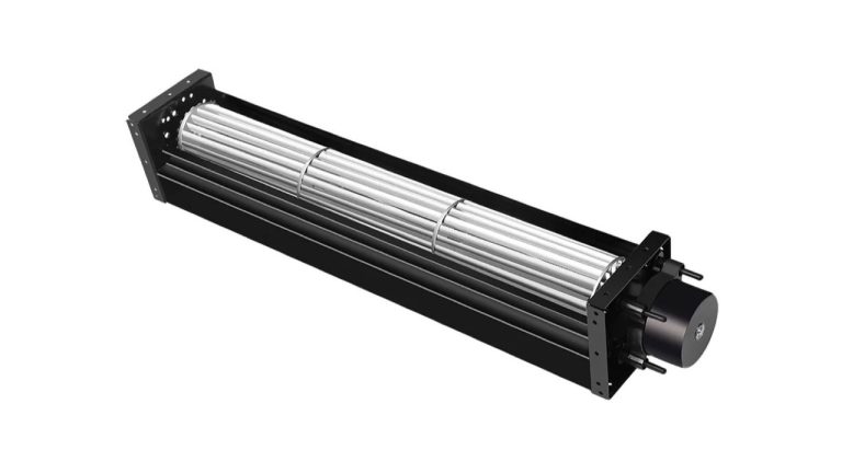
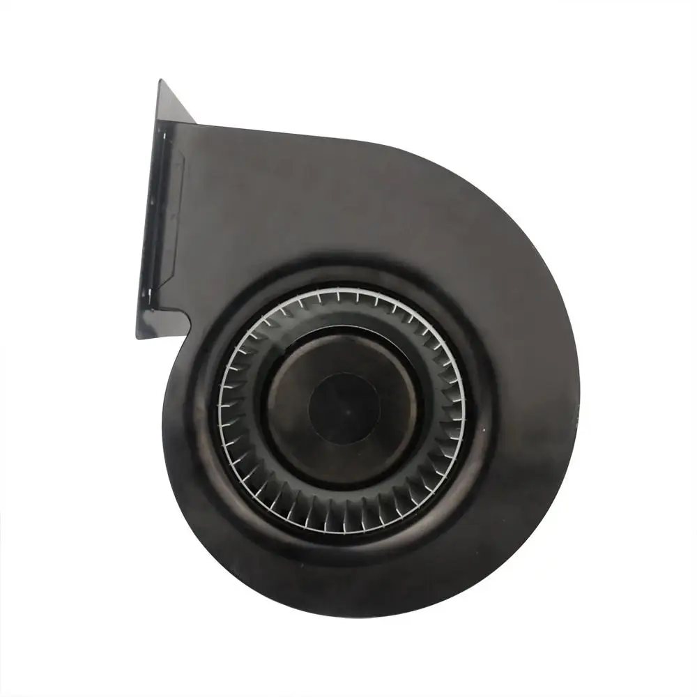
Architecture follows the required path. An axial fan may fit a short, open route; a centrifugal blower may suit a more restrictive or redirected route. A 140 mm DC forward-curved cabinet blower is a product-discovery example only. Its page confirms product identity and cabinet-cooling application context, not EV-charger compatibility, installed pressure, performance, certification or project suitability.
Make the Air Pass Through the Hot Parts
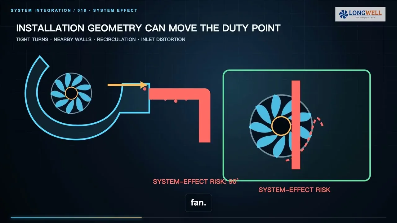
Arrange the intake, heat sources, heat sinks, fan and exhaust so the intended route is easier than every bypass. Separate intake and discharge zones, and add baffles or ducts where they are needed to prevent hot exhaust from returning to the inlet. Model cable bundles, service clearances and final panels because they can change the path after the prototype bench.
Measure more than one convenient air temperature. Place representative sensors at protected power modules, connectors, controls, inlet and exhaust, then investigate stagnant corners and downstream components. A thermal map makes bypass and hidden hotspots visible and provides a useful baseline when the filter loads, a fan slows or an internal assembly changes.
Coordinate Ventilation, Enclosure and Controls
Opening the cabinet boundary for airflow can change assumptions about rain, dust, salt, condensation, service and electrical safety. A fan component does not certify the completed charger, and component markings do not transfer automatically to the enclosure. The responsible system and certification teams must review the exact air openings, filters, drainage, installation instructions and protection strategy.
Define the environmental envelope that the actual installation must cover: ambient extremes, altitude, airborne contamination, water exposure, condensation and solar load where relevant. Controls should use representative temperature inputs, command fan speed, monitor credible status or tachometer feedback, raise alarms and move the charger to a validated derating or shutdown state when cooling capacity is uncertain. Universal thresholds do not belong here; they come from the released charger design.
Prove Degraded and Combined States
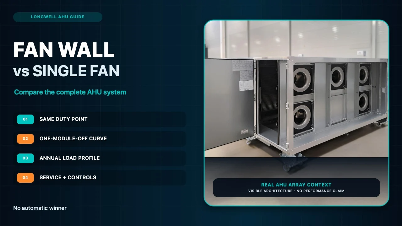
An extra fan does not by itself prove N+1 cooling. Test the defined fan-out state against component temperature limits, and combine it with other credible degradations that may coexist, such as a loaded filter, high ambient, supply tolerance or partial blockage. The evidence is the cabinet thermal result under the agreed duty cycle, not simply confirmation that another fan continues to spin.
Treat filter loading as a planned rise in system resistance. Define what operators will trend—pressure, airflow or a validated proxy, fan speed, hotspot temperature and alarms—and connect that evidence to a service action. Qualification should also cover control response, derating, shutdown and recovery rather than stopping at steady-state full load.
Release a Verifiable Cooling Package
Before choosing an exact fan, freeze the project inputs: heat-loss map, component limits, cabinet geometry, airflow route, clean and loaded resistance curves, ambient and density basis, supply and control interface, redundancy state, sound boundary, enclosure target and acceptance method. Ask the supplier to return the exact model suffix and revision, controlled curve, drawing, tolerances and operating limits.
Then verify the assembled cabinet across its defined operating envelope. Record component temperatures, airflow or a validated proxy, pressure, electrical input, control response and alarm behavior at agreed locations. Exterior charging-station photography and a product page can establish application or hardware context; neither proves the hidden air path, installed duty, ingress performance, certification or customer result. A defensible release connects measured losses, installed airflow and system-level validation.
Choose the right dc cooling fan
Longwell manufactures 38 dc cooling fans in-house. Send airflow, static pressure and voltage — an engineer replies with a matching model, performance curve and price within one working day.