If you are asking, “How much CFM do I need?”, do not start with a fan catalogue. First define what the air must accomplish, then calculate a volume-flow target, and finally pair that target with the pressure the installed system will resist. A fan rated at 1,000 CFM in open air may deliver much less after a filter, coil, grille, heat exchanger or duct is added.
This guide gives you a usable sizing path: choose the right calculation basis, keep the units straight, locate the duty point on a pressure-flow curve, and write an RFQ that a supplier can actually check.
What CFM tells you—and what it leaves out
CFM means cubic feet per minute. It is a volumetric flow rate: the volume of air crossing a defined plane in one minute. It is not air speed, static pressure, cooling capacity, sound level or efficiency.
Flow and average velocity are related by Q = A × v. If the same flow is forced through half the free area, the average velocity doubles. That change can alter pressure loss, throw, draft and sound even though the CFM number has not moved. The word average matters here; one velocity reading at the centre of a grille is not automatically a valid area average.
Pick the sizing basis before doing the arithmetic
There is no honest universal “CFM per square foot” value. The right starting method depends on the job:
- Room air replacement: use room volume and a required air-change rate. The ACH requirement must come from the applicable code, process, risk assessment or engineer—not from a generic online table.
- Occupied outdoor-air ventilation: use the governing ventilation procedure. Occupancy, floor area, zone distribution and system efficiency may all matter; room volume alone is not enough.
- Equipment cooling: begin with heat release, allowable temperature rise, design air density and the path air takes across the hot components. Recirculation and bypass can defeat a sound heat-balance estimate.
- Source capture or process exhaust: start with the capture velocity and opening geometry required for the contaminant or process, then account for duct and collection-system losses.
Write the chosen method and every input beside the result. That short note is often more valuable than another decimal place.
Worked room example: volume and ACH
For a simple air-change estimate, use:
CFM = room volume in ft³ × target ACH ÷ 60
A 20 ft × 25 ft × 10 ft room contains 5,000 ft³. If the project requirement is 6 ACH, the starting flow is 5,000 × 6 ÷ 60 = 500 CFM. Six ACH is an input to this example, not a recommendation for every room.
The 500 CFM result still needs a supply/exhaust balance, a distribution check and a pressure calculation. Partitions, short-circuiting between inlet and outlet, closed doors and an obstructed return can leave part of the room poorly served even when total flow is correct.
Convert CFM without mixing flow, speed and time
For unit conversion, 1 CFM equals approximately 1.699 m³/h or 0.4719 L/s. Therefore, 500 CFM is about 849.5 m³/h or 236 L/s. Keep the full precision in the calculation and round the final requirement to a level your inputs justify.
Do not convert feet per minute to CFM without an area. Do not compare a catalogue’s maximum CFM with a required m³/h value until you have confirmed both are volumetric flow under compatible test and air-density conditions.
Installed airflow is a duty point, not a free-air label
Filters, coils, guards, bends, dampers and ducts resist flow. The fan settles where its pressure-flow curve intersects the system-resistance curve. That intersection is the operating or duty point. Maximum airflow and maximum pressure normally occur at different ends of a curve, so they must not be combined as if they were one achievable condition.
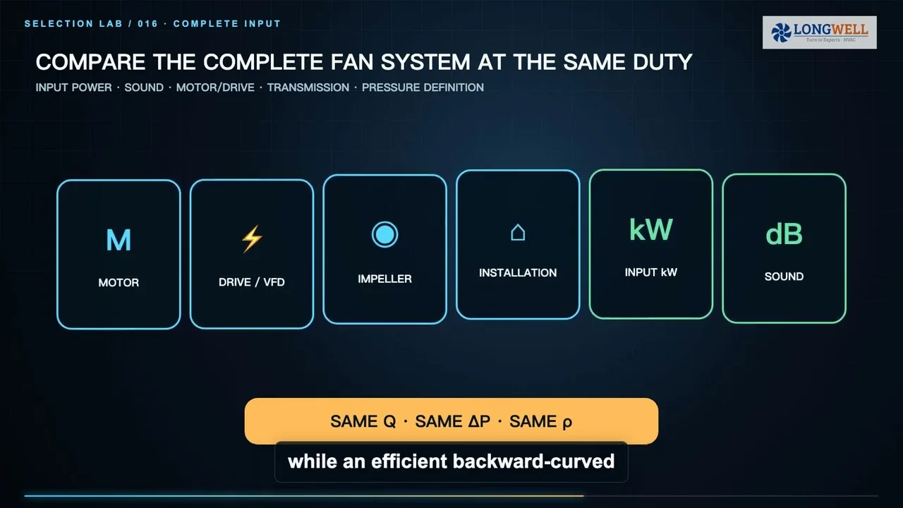
Ask whether the requirement uses static pressure or total pressure, and keep that definition consistent from calculation to test report. Then read airflow at the required pressure on the exact model, suffix, speed and revision curve. Our guide to reading centrifugal fan curves continues that process with chart examples.
A clean filter and a loaded filter create different resistance. If both states matter, specify both duty points or at least the end-of-service pressure allowance. Leaving this out is a common reason a fan looks adequate on paper but misses airflow later.
How to verify airflow after installation
State where airflow will be measured and what method will be accepted. A duct traverse, calibrated nozzle or airflow station can produce a representative volume result when used within its stated limits. A handheld reading at one convenient spot may be useful for troubleshooting, but it should not be promoted into a whole-system value without a valid averaging method.
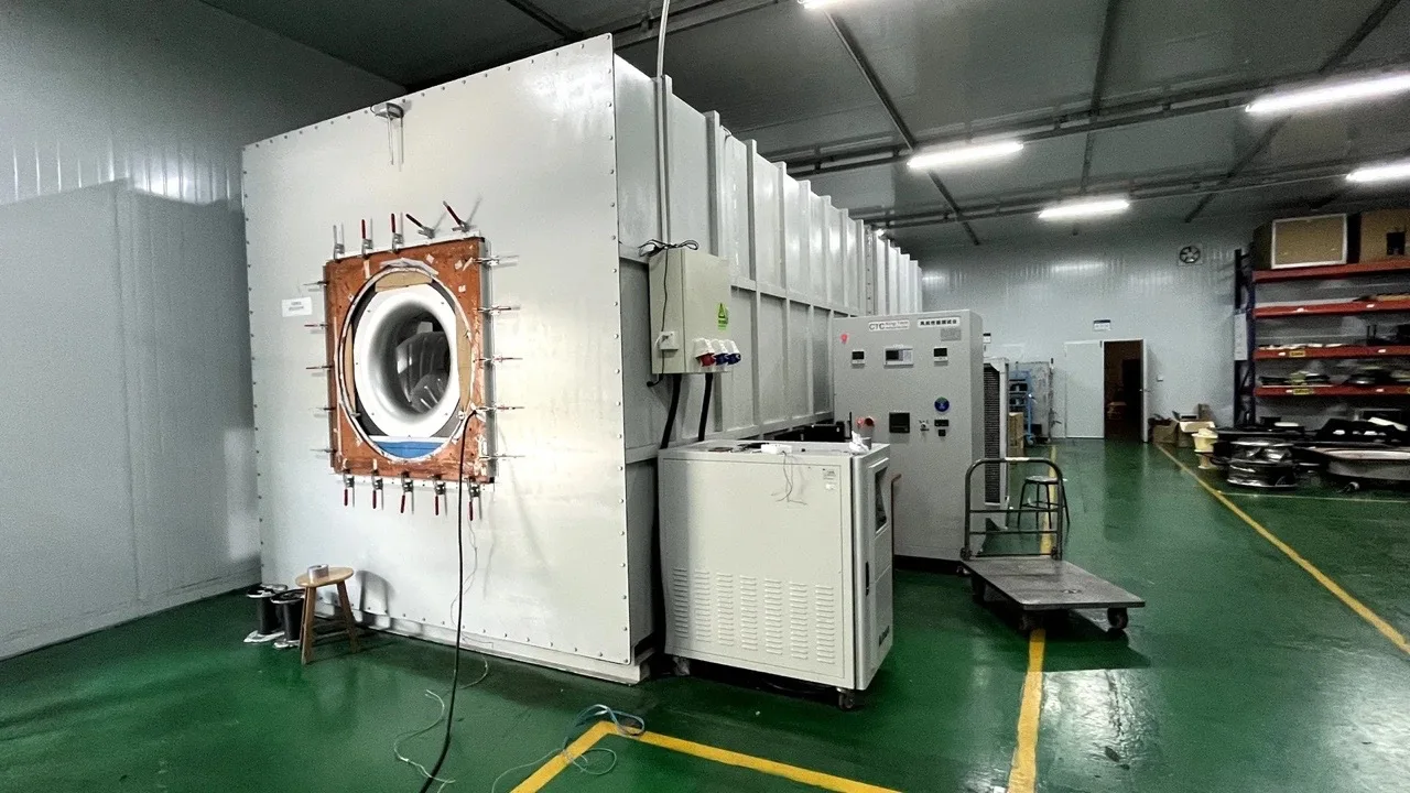
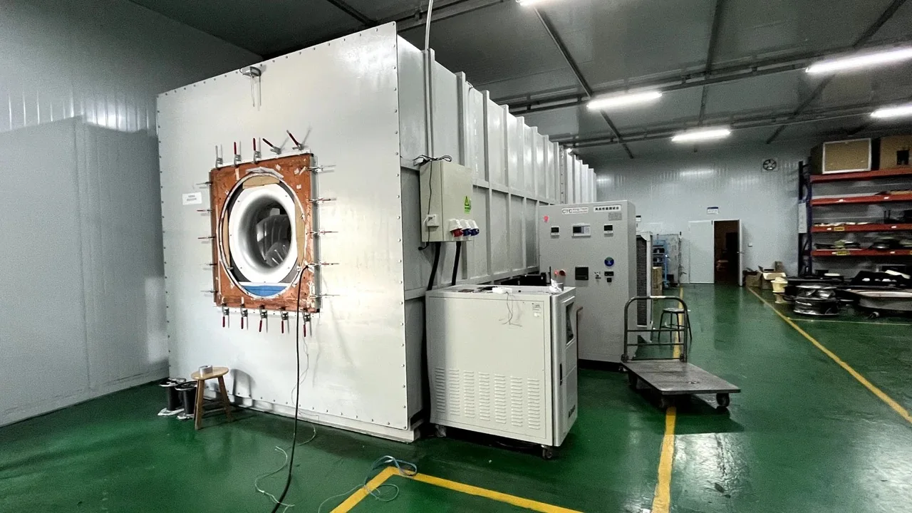
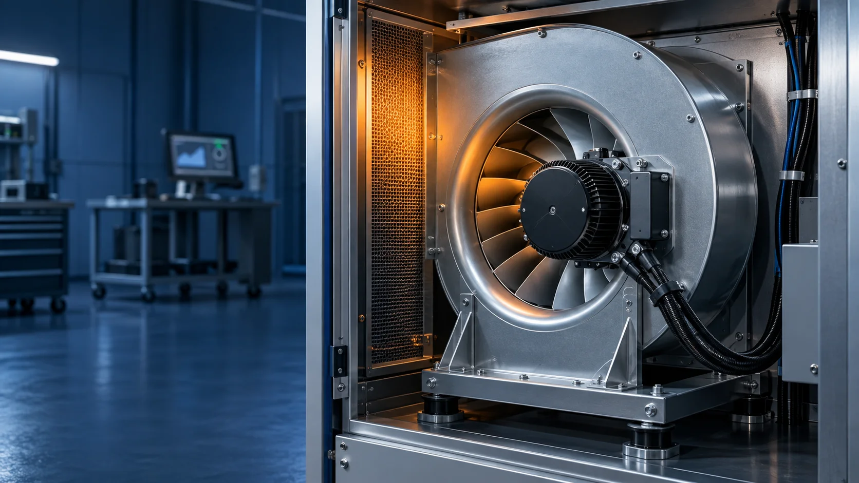
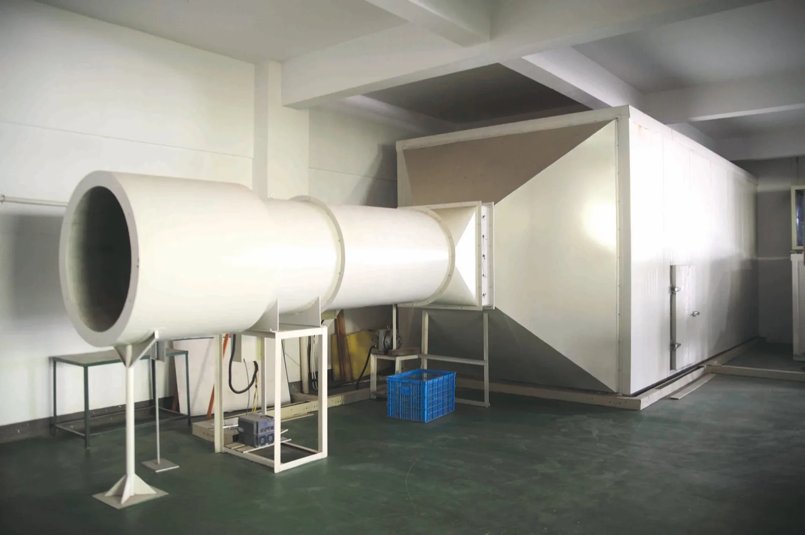
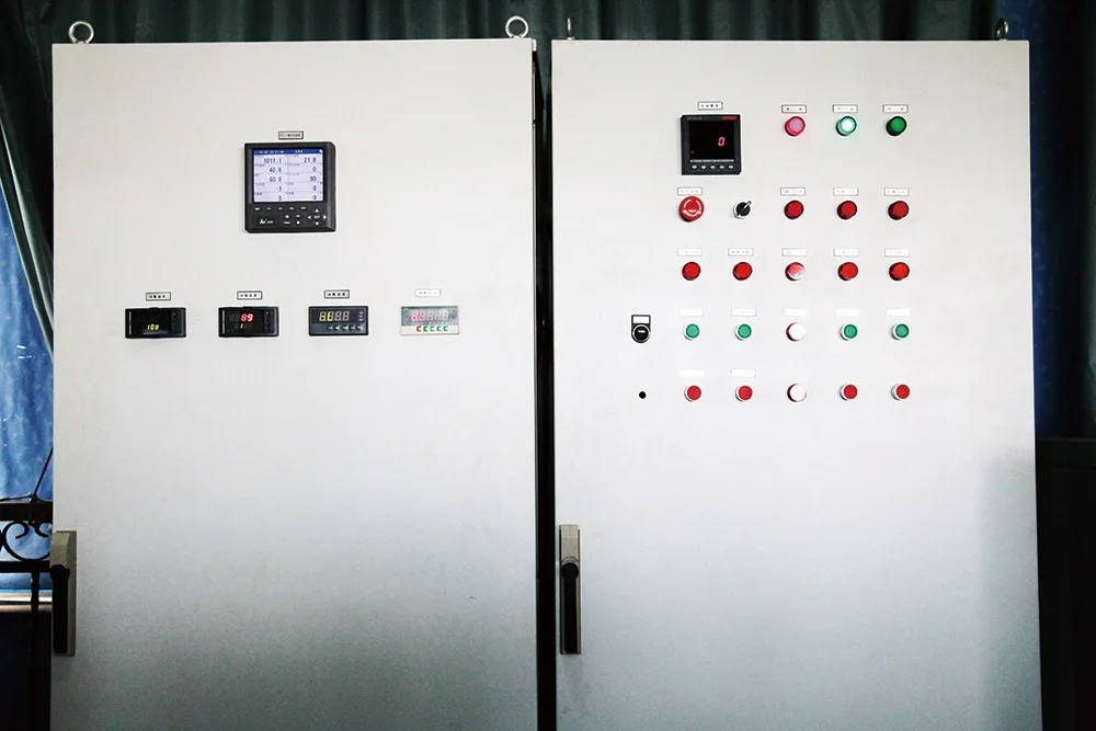
Record the instrument, measurement plane, free area, air temperature, pressure, density correction and system configuration. Note whether filters were clean or loaded and which dampers were open. The real LONGWELL test images here show physical duct/chamber and control-hardware context only; they do not claim accreditation or establish a result for any product.
Put these items in the fan RFQ
- Target airflow, with units and the calculation basis.
- Required static or total pressure at that flow.
- Air temperature, altitude or density, and any corrosive, wet or particulate content.
- Clean and dirty resistance states, duty cycle and redundancy requirement.
- Available inlet/outlet space, duct geometry, mounting orientation and dimensional limits.
- Electrical supply, approved control signal, speed range and failure behaviour.
- Sound limit and the exact test/reporting boundary.
- Exact model suffix, drawing revision, curve revision and acceptance test.
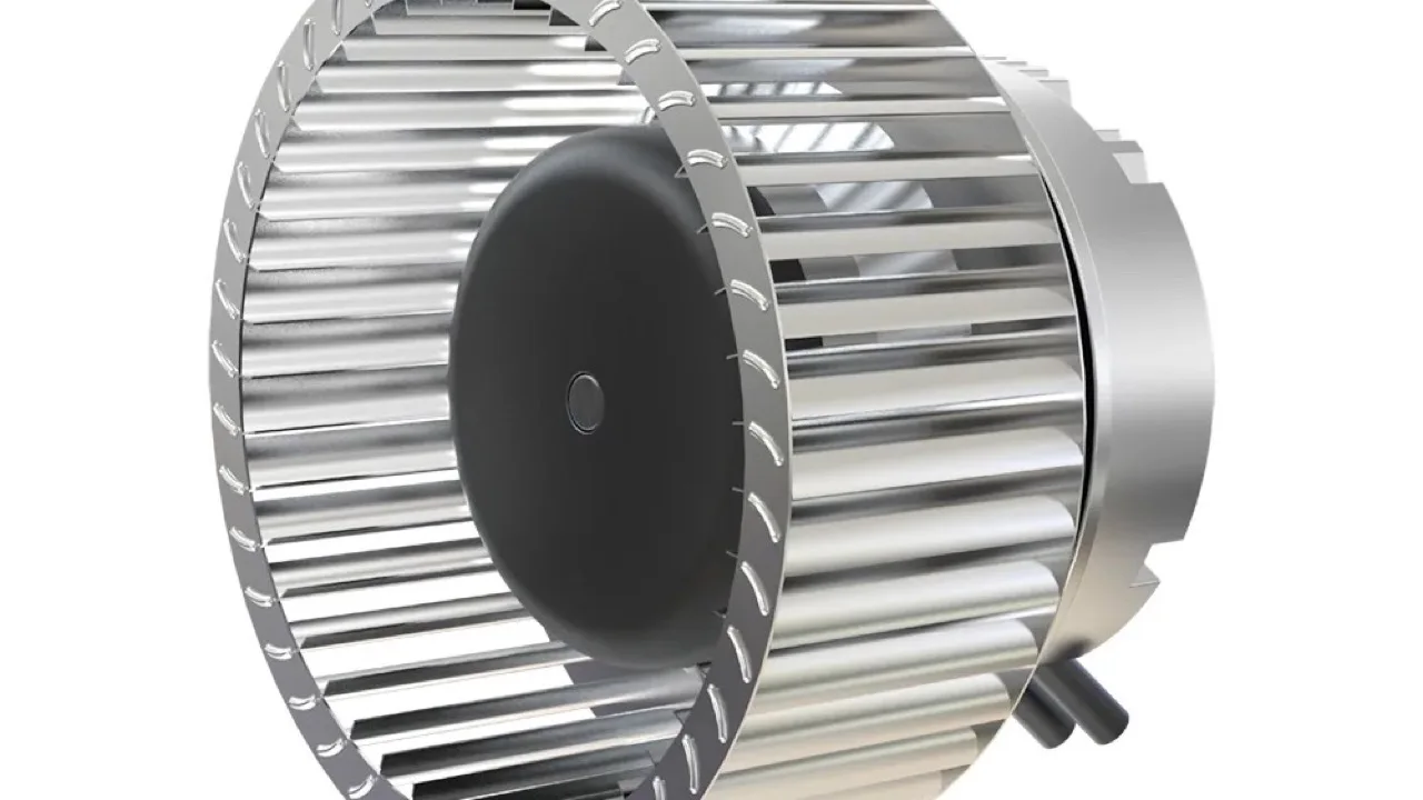
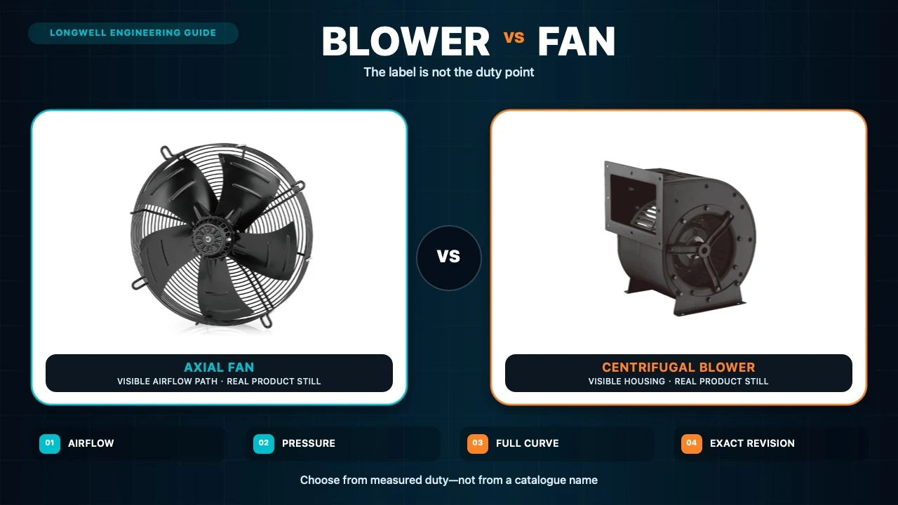
If the architecture is already confirmed as centrifugal, the current LONGWELL centrifugal fan family catalogue is a useful browse point. It is a family route, not proof that a particular model meets your duty point. Use the eight-step centrifugal fan selection checklist before narrowing the RFQ.
The final check is simple
A defensible selection connects three things: a transparent airflow calculation, a verified curve at the required pressure, and a representative installed or acceptance measurement. If one of those is missing, keep the result labelled as an estimate. CFM is essential, but it becomes procurement-ready only when pressure, air condition, distribution and measurement boundary travel with it.