A larger blower cannot capture welding fume that never enters the hood. If the plume crosses a worker’s breathing zone before reaching local exhaust, additional downstream airflow cannot undo the missed capture. Effective fume extraction begins at the source and follows the complete path through the hood, duct, air cleaner, blower, and discharge.
That path must be designed around the actual welding process, materials, coatings, consumables, worker position, and surrounding air movement. The objective is not simply high airflow, but reliable source capture under realistic work conditions. This guide gives industrial environmental teams and manufacturers a structured way to define hood performance, system resistance, blower duty, hazard boundaries, and commissioning evidence.
Begin With the Control Hierarchy and Source
Reduce or enclose the fume-producing process where practical, then place local exhaust as close to the source as the work allows. Appropriate respiratory protection remains necessary whenever extraction alone is insufficient. The exact process, base metal, coating, consumable, gas, vapour, and particle characteristics determine the industrial-hygiene and hazard review; a generic welding label is not enough.
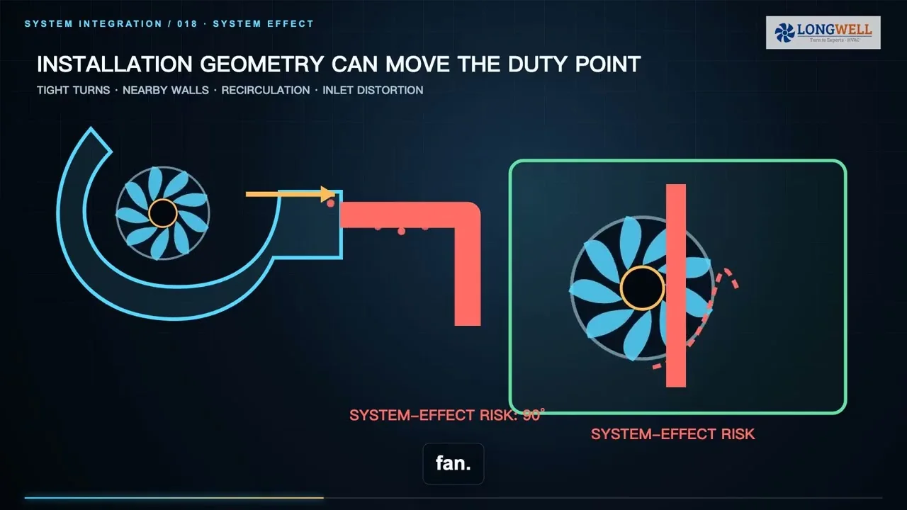
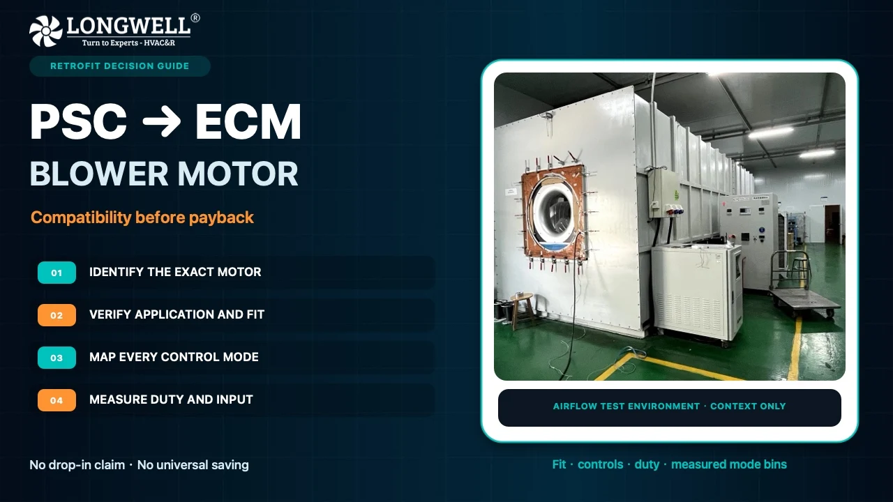
The available LONGWELL automated welding footage establishes visible automated metal-impeller welding and the source-process context only. It does not show a local exhaust installation or prove capture velocity, contaminant concentration, or worker-exposure performance. Any plume, breathing-zone, or capture-envelope graphics are explanatory animations, not computational fluid-dynamics results or exposure certification.
Place the Hood Around the Real Plume
Hood distance and orientation shape the capture envelope. A distant hood must influence more surrounding air, so position it so the natural plume travels toward the inlet while keeping the worker out of that path. The hood must also remain usable without obstructing the task. One capture-velocity number is not a universal rule for every welding operation.
Test realistic cross-drafts. Open doors, cooling fans, compressed-air jets, supply diffusers, and vehicle movement can bend a plume away from a well-positioned hood. Evaluate normal and worst credible worker positions rather than an empty, still workstation. Select a capture method that follows the source: a movable hood depends on correct repositioning, on-torch extraction stays close to the arc, a downdraft bench pulls away from the breathing zone, and a partial enclosure contains more of the plume. Each choice changes access, airflow, and pressure loss.
Build the Complete Dirty-System Pressure Path
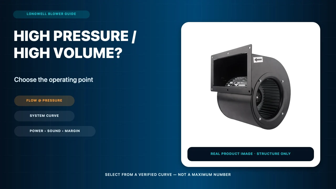
Follow captured air from the hood entry through flexible duct, elbows, branches, the air cleaner, blower, and final discharge. Every component adds resistance, and leakage can change both flow and containment. Maximum free-air airflow is not installed extraction airflow. The relevant blower operating point is where its curve intersects the complete system curve at the required flow.
Cleaner loading changes that system curve. As media loads, differential pressure rises and capture flow may fall. Define clean and credible loaded conditions, measure filter differential pressure, establish a qualified service limit, and verify hood capture after maintenance. Motor speed or electrical power alone cannot prove that the capture system is still working.
At the dirty-system operating point, compare airflow, pressure, power, speed range, sound, temperature, leakage, and service access. Maintain an evidence-based loaded-state margin without treating oversizing as a substitute for source capture or filter maintenance. Branch balancing and movable flexible ducts should be assessed in the configurations operators will actually use. Our fan-curve operating-point guide explains how to keep airflow, pressure, speed, density and power on the same test boundary.
Stop at the Hazard and Suitability Gate
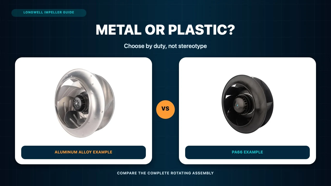
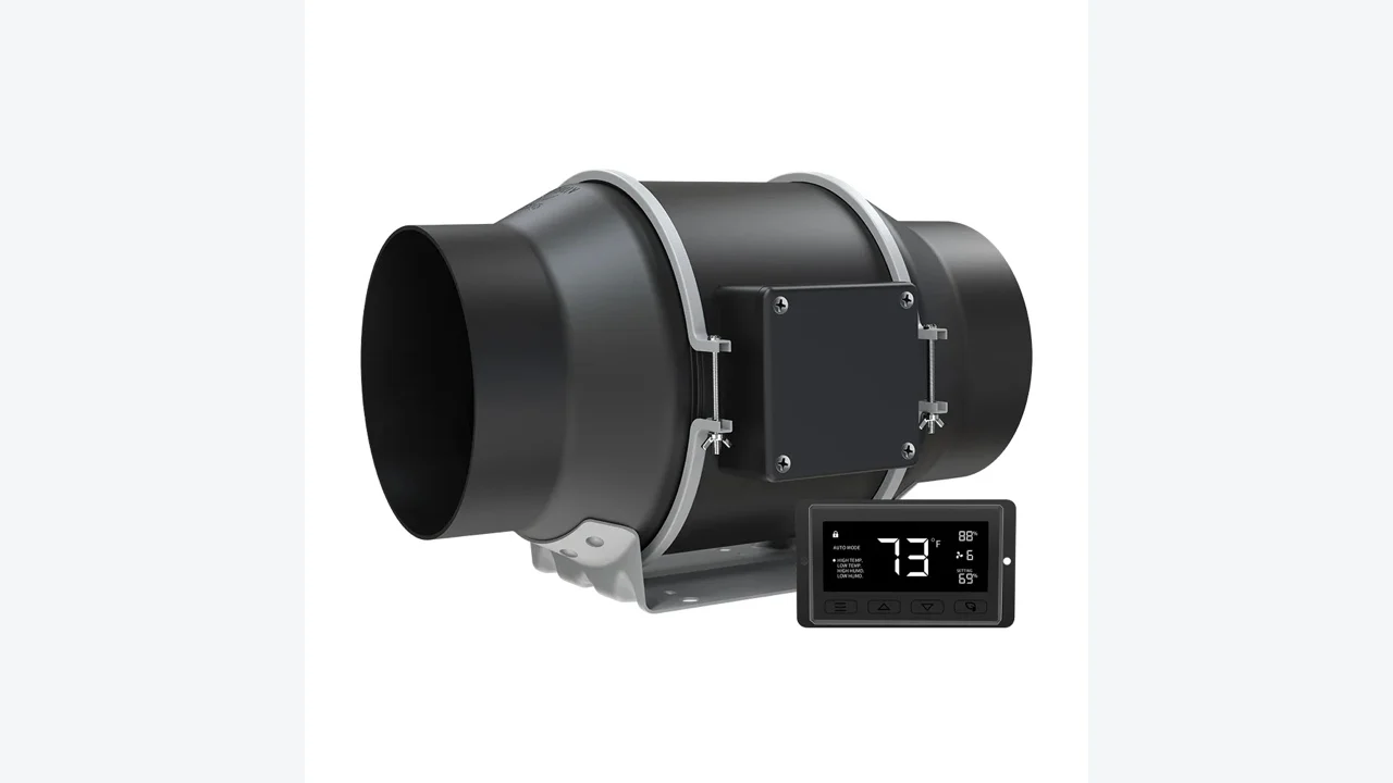
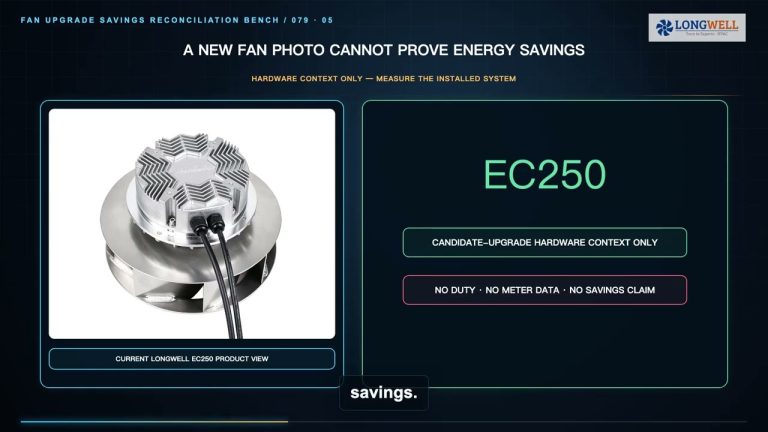
The LONGWELL EC250 image demonstrates visible backward-curved centrifugal architecture for clean-air-side discussion only. It does not establish direct-fume service, spark handling, corrosive-gas resistance, combustible-particle suitability, hazardous-location suitability, or approval for a specified welding-fume system. Hot fume, corrosion, sparks, and combustible material may change impeller construction, materials, motor placement, electrical classification, and required certification.
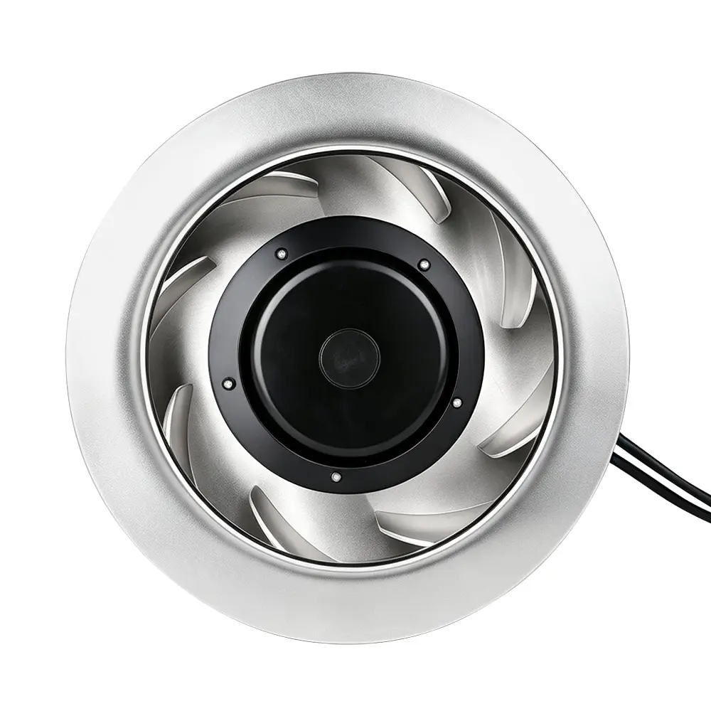
Discharge, recirculation, and make-up air are separate design decisions. Discharge contaminated air clear of intakes and occupied areas, or use a treatment and recirculation strategy specifically accepted for the process and jurisdiction. Replace extracted air with clean air without creating a cross-draft that breaks hood capture. A cataloged ventilation-fan option for welding-fume dedusting can support product discovery, but its page title and visible construction do not prove the required duty, spark control, material compatibility, certification or project suitability. Applicable exposure limits, fire and explosion controls, respiratory-protection requirements, electrical rules, and recirculation restrictions must be resolved by qualified personnel.
Commission Capture and Maintain the Evidence
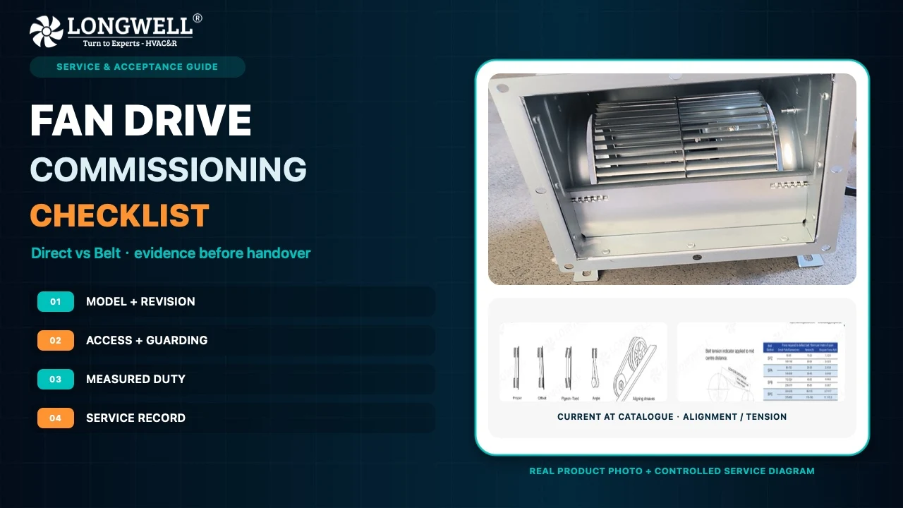
Commission the real workstation, not only the fan. Use an appropriate visualization method together with airflow and pressure measurements, filter differential pressure, fan status, and alarm tests. Check worker position, hood usability, cross-drafts, cleaner condition, discharge, and clean make-up air. Confirm that alarms and fault responses detect loss of credible extraction.
Repeat verification after filter service, duct changes, workstation rearrangement, process changes, or other modifications that can alter capture. A maintenance plan should preserve hood position, duct condition, cleaner performance, instrumentation, and operator usability. Exact intervals and acceptance limits belong to the validated process and local compliance program rather than a universal schedule.
A reviewable duty package should include the process and materials, hood geometry and position, worker locations, cross-draft conditions, duct-loss schedule, cleaner data, clean and dirty-system points, blower arrangement, discharge boundary, make-up air, alarms, maintenance basis, and acceptance tests. That evidence turns an air mover into a testable local exhaust system without converting product media into an unsupported safety or performance claim.
Choose the right blower
Longwell manufactures 247 blowers in-house. Send airflow, static pressure and voltage — an engineer replies with a matching model, performance curve and price within one working day.