A connected fan can report useful signals, but a dashboard does not diagnose a fault by itself. For a reliable smart-fan installation, first decide which controller commands the fan, which values are actually available on the chosen model, and what the equipment must do if communications fail. The video introduces local control, building-management supervision and optional remote monitoring; this guide turns those layers into a commissioning decision.
Separate local control from remote visibility
The fan drive, local sensors and protective functions belong at the equipment. A building-management system (BMS) may request a speed or operating mode, collect status and present alarms. A cloud connection may show the same supervised information to staff away from site. The project must define command ownership: two systems should not silently compete to write the same setpoint. It must also state which local condition overrides a remote request and what happens during a lost network connection.
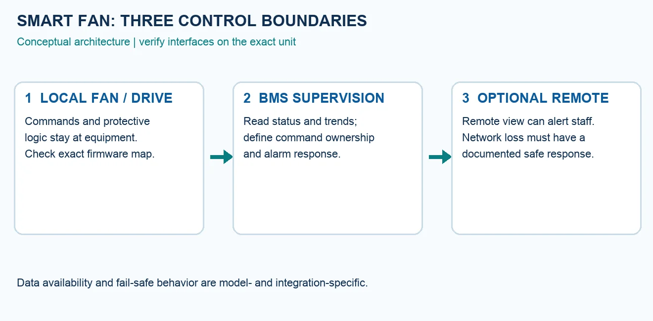
This architecture is a design method, not a claim that every LONGWELL EC fan includes a cloud service or a particular BMS port. The LONGWELL EC fan family is a starting point for candidate selection; confirm the exact model suffix, drive, firmware and available interface before specifying a supervisory sequence.
Read the exact protocol map before promising telemetry
A controlled example, the LWRS485-01 V2.0 protocol document containing AFL Modbus V2.09, lists readable status, running speed, power, voltage, current and operating time for its described controller. It also defines commands and serial settings. That is evidence of what this protocol revision describes, not a universal register map for every fan. A project engineer should match the installed hardware and firmware to its released protocol sheet, then verify each value’s address, function, unit, scaling and fault-code meaning on the actual device.
RS-485 is a physical communication layer; Modbus defines how messages are exchanged. Even when both labels appear on a submittal, the register map and available telemetry can differ between controllers. Our Modbus RTU fan-network guide explains the wiring, address and commissioning checks. Start with a read-only poll of one correctly addressed fan before enabling remote writes.
Build a baseline at a known operating condition
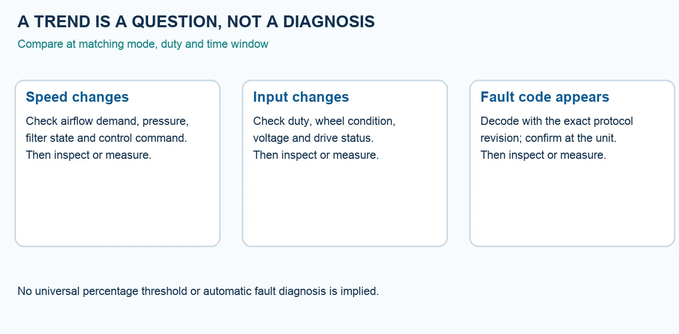
A speed or current trend means little without its operating context. At commissioning, record the airflow target, measured pressure, fan speed, input power or current if the controller exposes them, control mode, relevant sensor values and alarm state. Identify the filter condition and damper position. Keep the date, instrument method and exact equipment identity with those observations. Later comparisons should use matching demand and mode; otherwise an intentional setpoint change can look like deterioration.
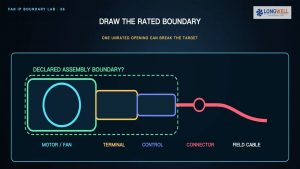
If a fan runs under constant airflow control, a rising speed may be consistent with increasing system resistance, but that interpretation needs the control sequence and pressure evidence. If the fan holds fixed speed, the same signal cannot measure filter loading. Likewise, current changes can reflect airflow, voltage, wheel condition or another cause. None of these readings alone confirms a dirty wheel or failing bearing. The diagram below is a question map for inspection, not an automatic fault classifier.
Assign alarms to an action, owner and test
For each available signal, write down who receives an alarm, how they confirm it and what action follows. A fault bit may call for a safe stop or local inspection; a slow trend may call for a scheduled pressure or airflow check. Set alarm levels from the application’s documented operating limits, measured baseline, sensor accuracy and acceptable response time. There is no defensible universal “10 to 15 percent above baseline” rule for all EC fans. Test the alarm route, acknowledgement and restoration at commissioning rather than assuming a dashboard notification was delivered.
For a fan wall, also record the intended response when one fan is unavailable: which unit or controller reallocates duty, whether the remaining fans can meet the required airflow, and how the BMS reports degraded operation. Those outcomes require system design and measured acceptance checks. A single fan’s Modbus register list cannot establish a complete array-control capability.
Keep the remote layer secure and recoverable
Remote monitoring should have a named operator, defined access, a change record and a recovery plan. Separate observation from setpoint authority. Document how credentials, gateway updates and outages are handled under the site’s operational-technology policy. During a communications-loss test, verify the fan and local controls enter the project-defined state while the BMS records the loss. A remote dashboard may make an alarm easier to see; it must not be the only place a safety-relevant decision exists.
Choose a useful pilot rather than a larger dashboard
Pick one equipment group with a clear maintenance question. Obtain the exact fan and controller documentation, confirm the available read points, collect a measured baseline and agree on one alarm-response owner. Run a read-only trend first. Add commands only after the control hierarchy, fail-safe behavior and commissioning test have been approved. The separate 0–10 V, PWM and Modbus comparison helps choose the interface; the maintenance guide helps turn a verified issue into an inspection plan.
The practical outcome is a traceable fan-control specification: named command owner, exact protocol revision, measured baseline, scoped alarm logic and a tested loss-of-communications response. These inputs let a reviewer decide whether remote monitoring adds useful action for this installation without claiming that connectivity itself predicts faults or extends service life.