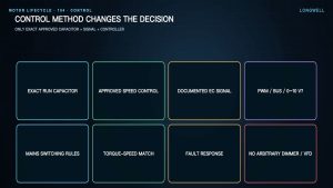
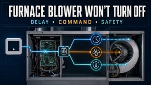
Before connecting an inline fan to a switch, timer or humidistat, establish what the control actually switches. It may carry the motor load, provide a dry contact, send a low-voltage command or communicate with a dedicated controller. Those are different interfaces. Similar wire colours, connectors or control knobs do not make them interchangeable.
This guide helps you prepare a control specification and review a proposed installation. It is not a universal wiring diagram. The exact fan and controller manuals, supply arrangement and applicable installation requirements govern the connections; electrical work belongs to qualified personnel.
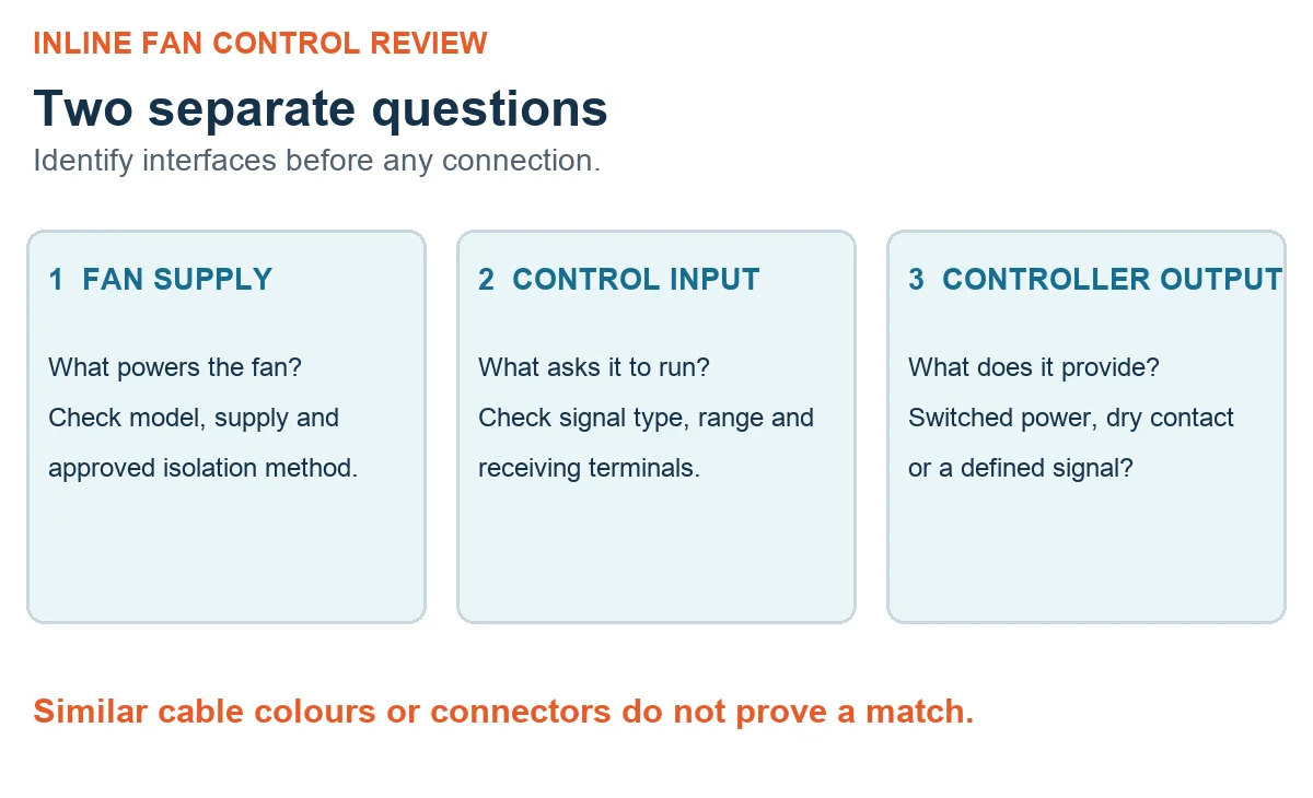
Separate the fan supply from its control input
Start with the fan’s complete model identification and the matching document revision. Find the supply requirements and, separately, the control-input specification. Then do the same for the proposed switch, timer or humidity controller. Write down which device supplies power, which device issues a command and what each terminal is intended to do.
An input marked for a control signal is not an invitation to connect mains power. Nor does a contact output necessarily supply a voltage. Check whether the interface expects a switched supply, a volt-free contact, a defined analogue or pulse signal, or a manufacturer-specific connection. If the documents do not establish a match, resolve that question before installation.
Check the switch rating against the job it will do
A switch controlling the motor supply needs a different assessment from a switch commanding a control input. Review the documented voltage, load type, current and starting characteristics, along with contact ratings and the required poles. A headline current marking alone does not establish suitability for a motor load.
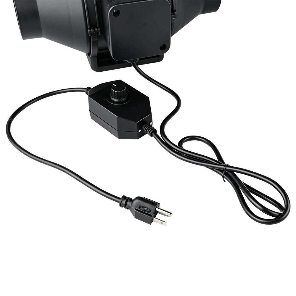
Also check the permitted enclosure and environmental conditions. The controller’s mounting position, cable entries and protection from moisture must suit the actual installation. Do not select a device solely because its front panel looks like the existing one. Keep the approved circuit arrangement with the component list so the electrician can review the whole combination.
Define what the timer does when the switch changes
“Fit a timer” is an incomplete control requirement. Is the intention a scheduled operating period, a delayed start or continued ventilation after a manual command ends? State the intended sequence in plain language before choosing the device. Then check whether the selected fan and controller support that sequence using their documented connections.
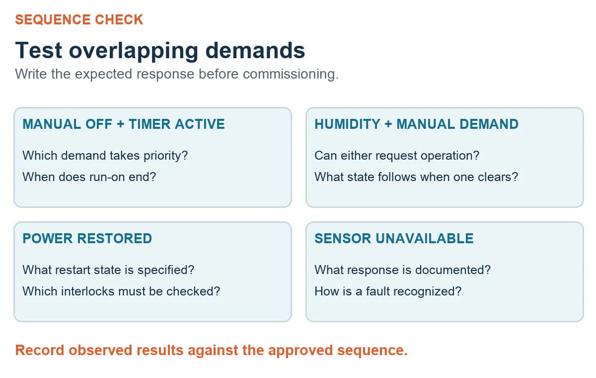
Consider a manual switch and a run-on request together: what should happen when the user turns the switch off while a timed period is active? Which command has priority? What happens after a supply interruption? These are design questions, not reasons to improvise additional connections. There is no single delay setting appropriate to every room or ventilation duty.
Specify the humidistat’s role and failure behaviour
A humidity controller adds a demand signal, but the required response still needs definition. Decide whether it enables ventilation, requests a different operating state or works through another controller. Confirm the output type against the receiving input. “Humidity control” on a product description does not establish electrical compatibility.
Record the intended sensor position and operating range using the applicable documentation and project requirements. Define the threshold and switching behaviour for the application rather than copying another installation’s settings. Include what should happen if a sensor fails or its signal is unavailable. If manual, timer and humidity demands overlap, the final sequence should explain which demand takes priority and how normal operation resumes.
Keep maintenance isolation separate from normal stopping
A wall switch, timer output or stop command must not be treated as proof that the equipment is electrically isolated. Before access or maintenance, qualified personnel must follow the equipment-specific isolation and verification procedure and the applicable requirements. This article does not describe working on live wiring.
The installation review should also cover protective earthing where required, neutral arrangements, separation of voltage classes, cable protection, strain relief and enclosure closure. Check the selected equipment’s documents rather than relying on conductor colour or a generic diagram. Resolve condensation exposure and access for maintenance before the installation is signed off.
Commission the sequence, not only the on/off button
Prepare the expected result for each approved test before commissioning. Record the observed response and any deviation. Testing only that the fan starts leaves timer interactions, humidity demand and restart behaviour unexamined.
| Condition to review | What the agreed test should establish |
|---|---|
| Manual demand | The intended start, stop and override behaviour |
| Timer demand | The specified sequence, including overlapping manual commands |
| Humidity demand | The response to the configured sensor conditions and unavailable signals |
| Power restoration | The documented restart state and relevant interlocks |
| Normal operation | Correct airflow direction and stable operation within approved limits |
Use the manufacturer’s approved test methods and project acceptance criteria. For broader installation context, the duct fan installation and application guide is background reading, not a replacement for the selected model’s wiring instructions.
Hand over a matched set of documents
Keep the fan and controller identities, approved wiring document, control sequence, final settings and commissioning record together. A later replacement should be checked against that set; appearance alone is not a sound replacement criterion.
When discussing a new selection, the Longwell EC inline duct fan range provides a starting point for identifying a series. Confirm the actual control option for the supplied configuration. Prepare the duct arrangement, airflow requirement, available supply, proposed controller and intended sequence so the specific combination can be reviewed.
Choose the right duct fan
Longwell manufactures 254 duct fans in-house. Send airflow, static pressure and voltage — an engineer replies with a matching model, performance curve and price within one working day.