0–10V, PWM, and Modbus can all request an EC fan speed, but they behave differently when a cable is noisy, a controller loses power, or a building system needs evidence that ventilation is actually operating. The right choice depends on the complete command, feedback, wiring, failure, and commissioning boundary.
No interface should be selected from habit or a generic wiring diagram. The exact fan model, controller, electrical limits, signal reference, communication settings, feedback needs, cable environment, fan quantity, and required safe state must be defined first. This guide gives integrators and controls engineers a disciplined way to compare the three approaches.
Start With a Model-Specific Interface Passport
Collect the exact fan and controller documents before designing connections. Confirm the power supply, signal type, reference terminal, input limits, logic polarity, PWM voltage and frequency requirements, protocol, register map, address range, baud rate, parity, termination, and available feedback. Never infer a pinout or terminal function from wire color or another product family. A broader EC fan selection guide can help frame the application and duty questions before the interface decision.
Define the required speed range, control resolution, cable length and environment, number of fans, BMS or PLC platform, feedback and alarm needs, local override, safe fallback, and restart behavior. This passport makes compatibility testable and prevents a familiar connector from being mistaken for an approved interface.
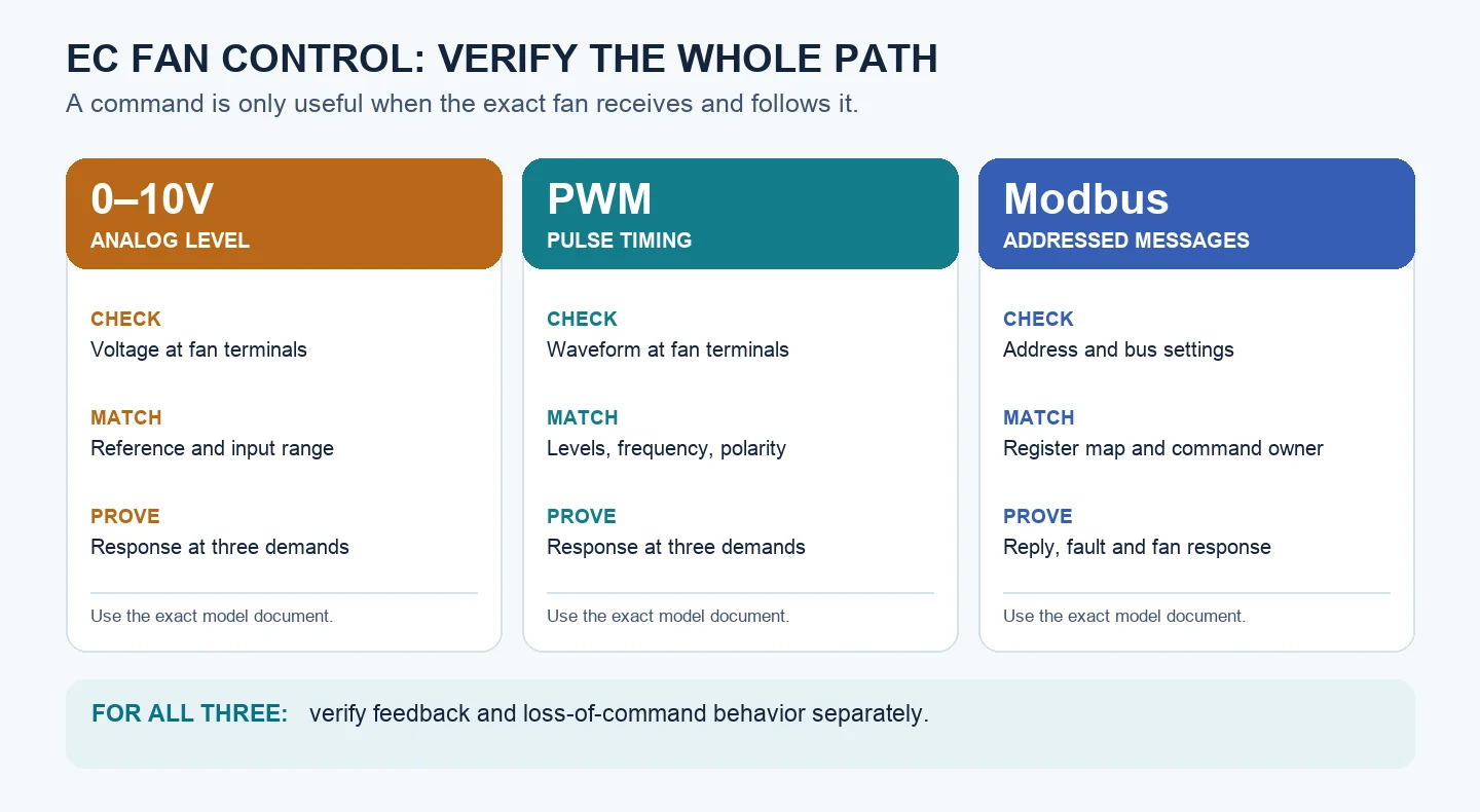
Evaluate the Complete 0–10V Path
With 0–10V control, speed demand is represented by an analog voltage referenced to the fan’s specified signal ground. The method is direct and widely integrated, but the voltage at the controller is not necessarily the voltage that reaches the fan. Cable resistance, input impedance, ground offset, shielding, routing, and electrical noise can change the received command.
Verify the analog signal at the fan terminals across minimum, intermediate, and maximum demand. Check the manufacturer’s defined behavior below, within, and above the valid input range. For multiple fans, consider source loading, reference errors, isolation, and whether a shared command remains within the controller and fan limits. Do not assume that an open wire or zero voltage produces a universally safe state.
Verify PWM as an Electrical Waveform
PWM represents demand through duty cycle, but duty cycle is only one part of compatibility. The receiving fan still requires specified voltage levels, frequency range, polarity, reference, input circuit, and edge behavior. A pulse train accepted by one model may be unsuitable for another even when the percentage displayed by the controller looks correct. For background on the integrated electronics behind this control boundary, see the EC fan technology guide.
Measure the waveform at the fan terminals rather than only at the source. Confirm minimum, intermediate, and maximum commands, cable effects, electrical reference, and response to missing pulses. Multi-fan fan-out requires verified source capacity and input compatibility. Define whether loss of PWM creates a stop, fallback speed, latched fault, or another model-specific response.
Design Modbus as a Managed Network
Modbus can carry addressed commands, status, alarms, and operating data over one network. That flexibility adds configuration responsibilities: register mapping, unique addresses, baud rate, parity, bus topology, termination, biasing, timeouts, retry logic, and service replacement all need an approved plan. A valid message confirms communication, not airflow.
Define ownership of each command and register, startup values, write limits, watchdog timing, communication-loss fallback, alarm propagation, and power-recovery behavior. For arrays, decide whether fans share a group command or receive individual setpoints. Maintain address records so a replacement module cannot duplicate another device or receive an unintended command.
Separate Wiring, Feedback, and Physical Proof
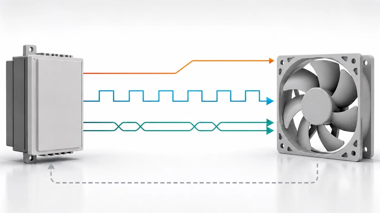
Keep mains power, analog signals, pulse signals, and the differential bus under their respective routing, cable, shielding, grounding, and bonding rules. Those details remain project- and model-specific. The illustration above only separates command and feedback concepts; it does not define terminals, conductors, protocol compatibility, cable construction, or a safe installation.
Feedback is a separate design question. A tachometer or frequency output may indicate rotation or speed. Modbus may expose speed, power, temperature, or alarm registers when the exact model supports them. Command acknowledgement or speed feedback is not proof of airflow; critical processes may require independent pressure, airflow, or process sensors.
Commission end to end with qualified personnel following the product and electrical instructions. De-energize for wiring checks, confirm the exact terminal map, energize safely, and sweep minimum, intermediate, and maximum commands. Record terminal signal, fan response, speed, current, relevant airflow or pressure, feedback, alarms, open-wire or communication-loss behavior, local override, safe stop, and power recovery.
The final handover package should contain the exact models and manuals, wiring drawing, signal limits, cable and grounding design, network settings, address and register list, fan grouping, feedback strategy, fail-safe state, commissioning records, and acceptance criteria. The current EC fan family is a discovery endpoint only; exact model documentation and project acceptance evidence must control the interface decision.
Choose the right speed regulator
Longwell manufactures 5 speed regulators in-house. Send airflow, static pressure and voltage — an engineer replies with a matching model, performance curve and price within one working day.