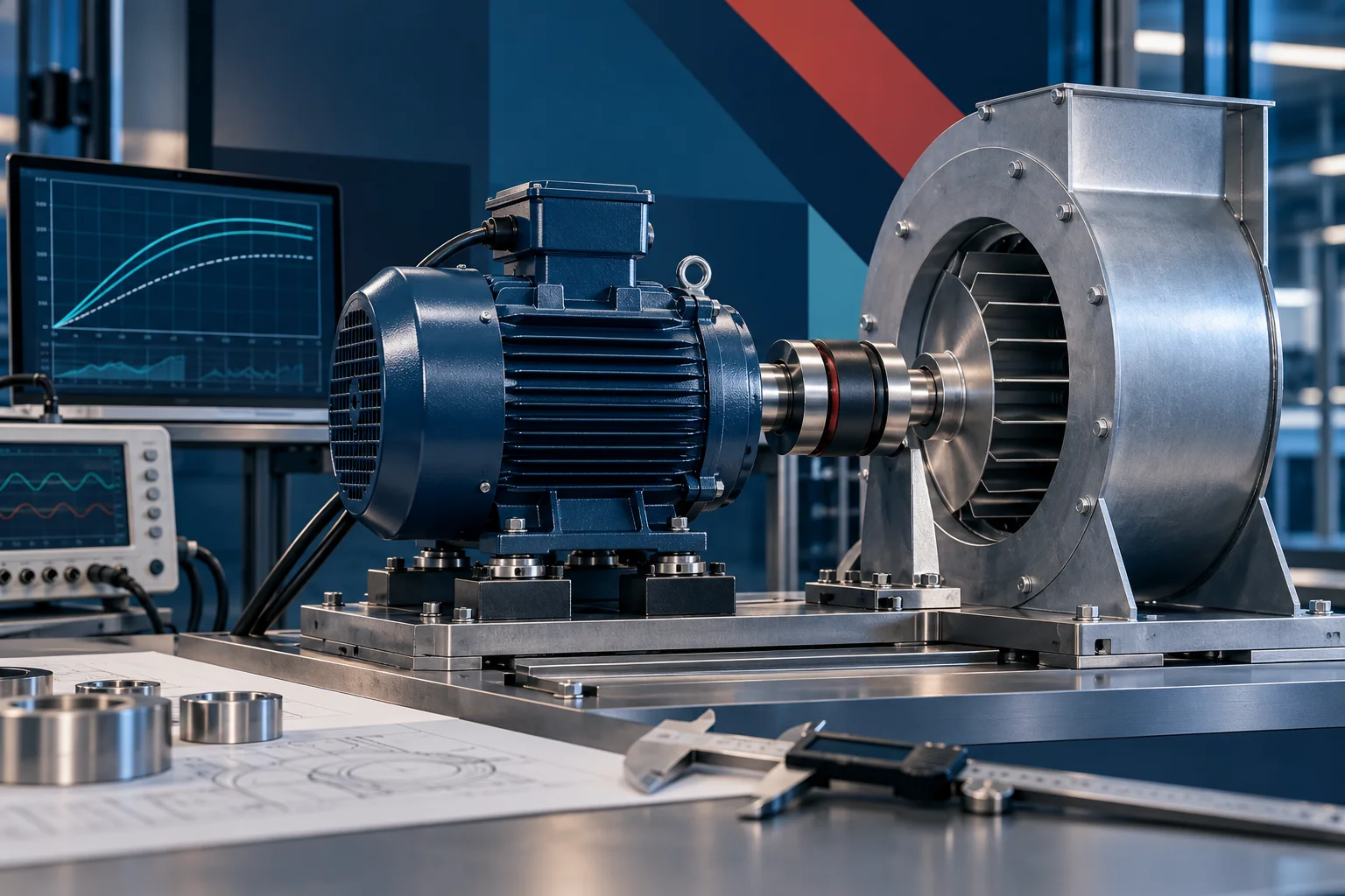
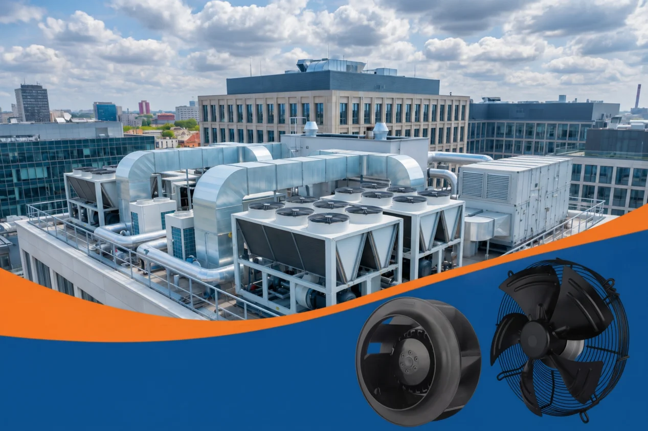
Retrofitting an old AC fan to EC is a controlled system changeover, not a motor swap. This workflow starts after a technically suitable EC candidate has been shortlisted. It helps the installation team translate that choice into a reversible mechanical plan, a verified electrical-and-control interface, and an acceptance record. It does not replace fan selection, site safety procedures, or the exact product manual.
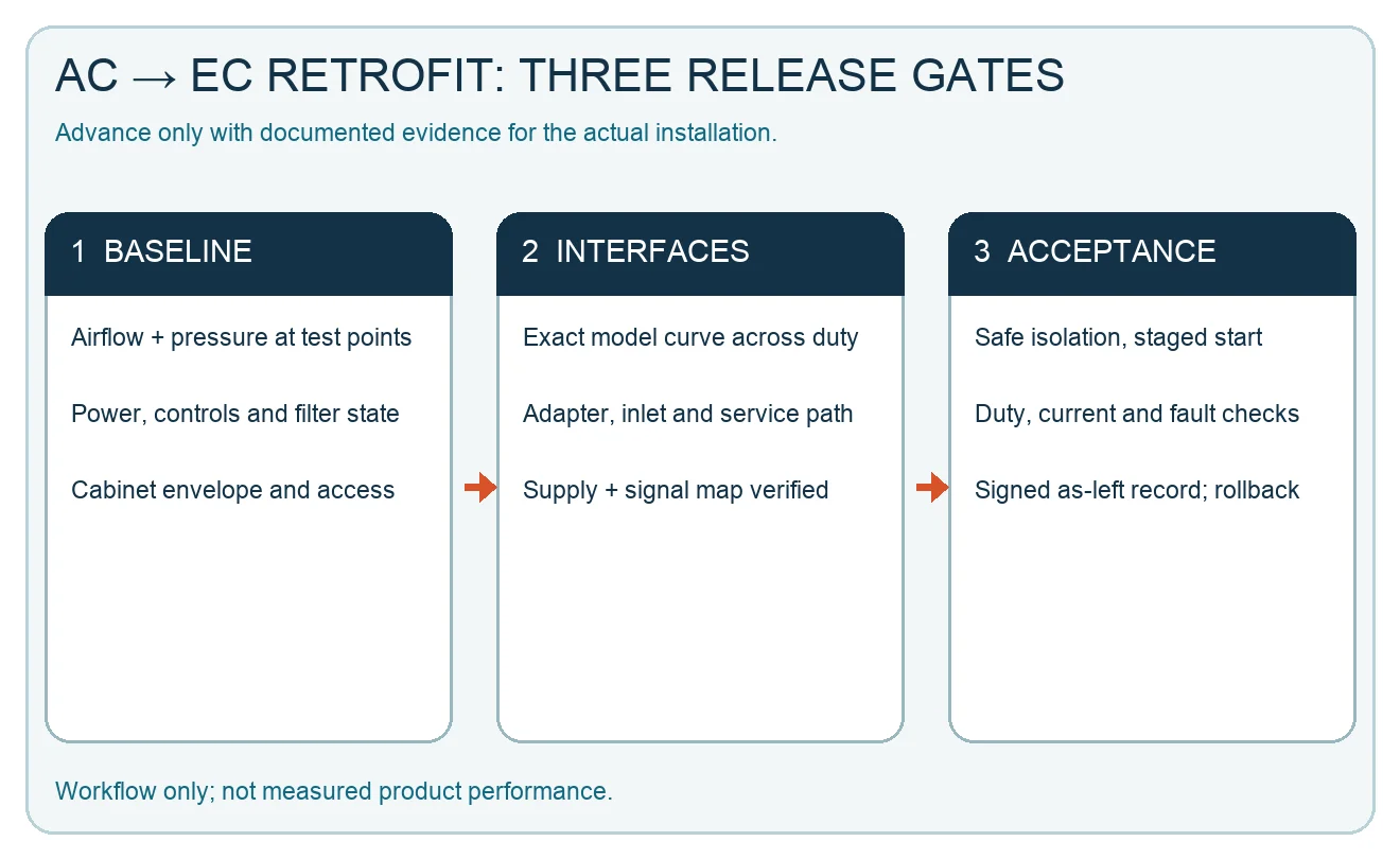
A fan that fits the opening can still miss the required duty, create bypass leakage, conflict with the controller, or become impossible to remove for service. Keep five gates connected from survey to handover: air duty, mechanical fit, electrical supply, controls, and safe work.
1. Freeze the Baseline and the Change Boundary
Record the existing system while it can still operate. Capture airflow, the agreed static-pressure boundary, electrical input, speed, control command, filter condition, damper position, and any useful vibration or sound observations at minimum, normal, and peak modes. Name the instruments and measurement locations. The baseline is an acceptance reference, not proof that the old fan was correctly selected.
Define exactly what will change: fan assembly, adapter, isolators, guards, cabling, protective devices, control logic, sensors, and access panels. Also list what remains. Before hands-on work, authorized personnel must apply the site hazardous-energy procedure, release stored energy, and verify isolation. A software stop or zero-speed command is not an energy-isolating device.
2. Build a Reversible Mechanical Plan
Survey the opening, rails, inlet plane, outlet direction, door swing, lifting route, cable route, and removal path. Check the adapter geometry, mass and center of gravity, fasteners, vibration isolation, guards, sealing, and service clearances. Photograph obstructions and dimension the cabinet with doors, filters, and access panels in their normal positions.
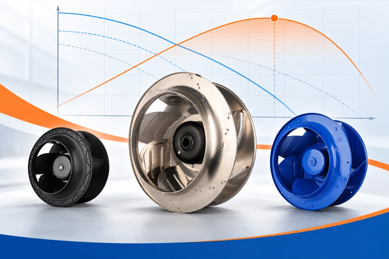
Protect the air path as carefully as the mounting. Inlet blockage, sharp transitions, nearby elbows, swirl, and bypass leakage can shift the installed operating point away from catalog data. Use the fan-curve operating-point guide to keep airflow, pressure, speed, power, and density on a consistent boundary. The page explains method; it does not approve a fan for this project.
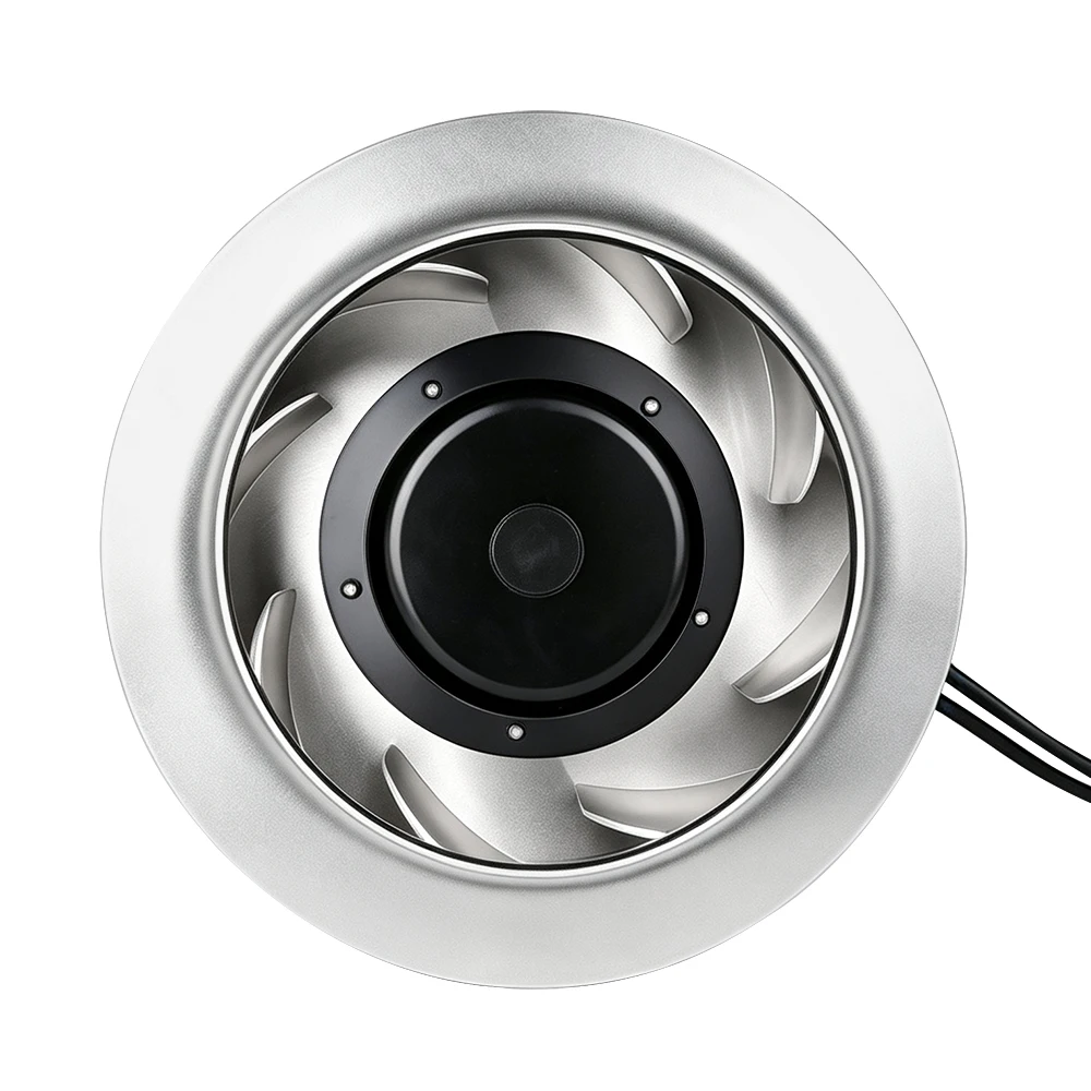
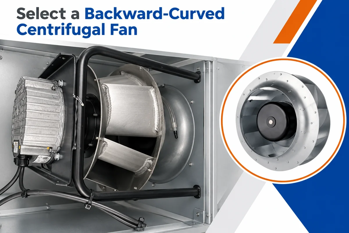
The pictured EC250 family member is only a visual reference. Compare the exact released model drawing and curve with the measured cabinet envelope and duty schedule before choosing a replacement.
3. Sign Off the Electrical and Control Handshake
Create an interface sheet from the exact released fan documentation and project drawings. Confirm supply voltage, phase, frequency, maximum input current, branch protection, disconnect, protective earth, cable rating, and available fault conditions. Do not reuse a protection device merely because measured current may be lower at one operating point.
For controls, define run enable, speed demand, run feedback, fault output, safe-stop state, reset logic, and recovery after power interruption where required. Verify each signal at both ends. Never infer terminal function, signal range, wire color, grounding, or fail-safe behavior from another model or from a photograph. If a supplier package is needed, the centrifugal fan retrofit-package page is a product-discovery endpoint only; it proves no compatibility or result.
4. Install with a Defined Rollback Point
Freeze controller settings, label every connection, retain the baseline records, and document the removed assembly before modifying the cabinet. Clean and inspect the structure, fit adapters and seals, mount and tighten components to the approved instructions, route and protect cables, restore guards, and obtain any required independent inspection before energization.
Keep the old assembly and reversible interfaces until the new installation passes acceptance. Define the latest safe rollback point, who can authorize rollback, and which temporary conditions are prohibited. A recoverable plan reduces pressure to accept an installation merely because the old equipment has already been discarded.
5. Commission Against Written Go/No-Go Limits
Begin with visual, mechanical, clearance, insulation, and protective-earth checks. Energize at the lowest approved command, confirm rotation and abnormal sound, then move through intermediate and design modes. Measure current, airflow, the agreed pressure boundary, vibration, and electrical input. Exercise run/stop commands, alarms, loss of demand, safe stop, and power recovery when they are part of the released control sequence.
Accept the retrofit only against the written duty schedule and equipment limits. When an energy case is needed, use the AC-to-EC ROI boundary guide to compare equivalent operating hours and electrical boundaries. Do not promise savings from a nameplate, free-air value, or unmatched before-and-after readings.
6. Hand Over an As-Left Technical Record
The final package should include baseline readings, the approved duty schedule, exact fan identity and revision, fit drawings, adapter and sealing details, wiring, protection settings, control sequence, inspection records, commissioning measurements, alarm tests, operator guidance, maintenance access, spares, and rollback disposition. Record the final controller values as left, not only the intended values.
This endpoint is deliberately different from choosing an EC fan or calculating a business case. The retrofit is complete when qualified stakeholders can reproduce the installed configuration, judge it against agreed limits, service it safely, and understand what evidence supports acceptance.