Fan laws answer a deceptively simple question: if a fan runs faster or slower, what should happen to airflow, pressure and shaft power? For the same fan at a fixed impeller diameter, airflow changes in direct proportion to speed, pressure changes with the square of speed, and shaft power changes approximately with the cube. The arithmetic is quick. Knowing when the estimate is trustworthy takes more care.
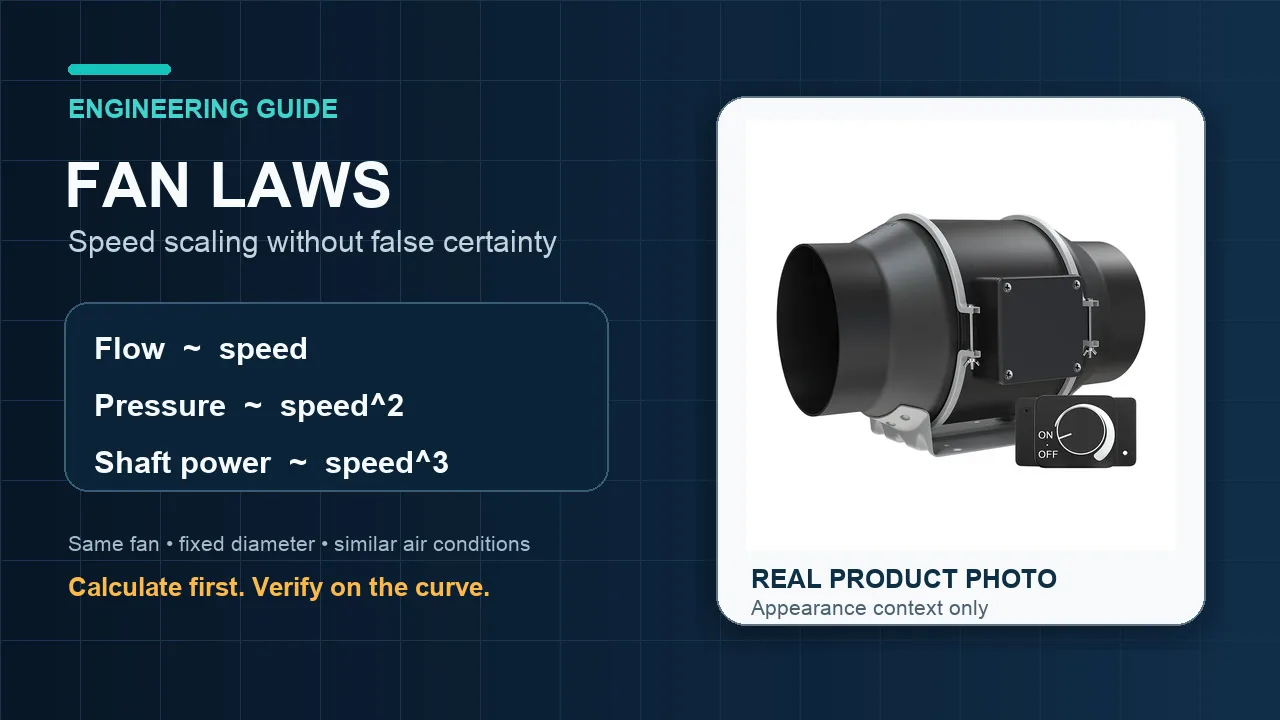
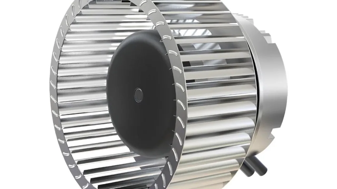
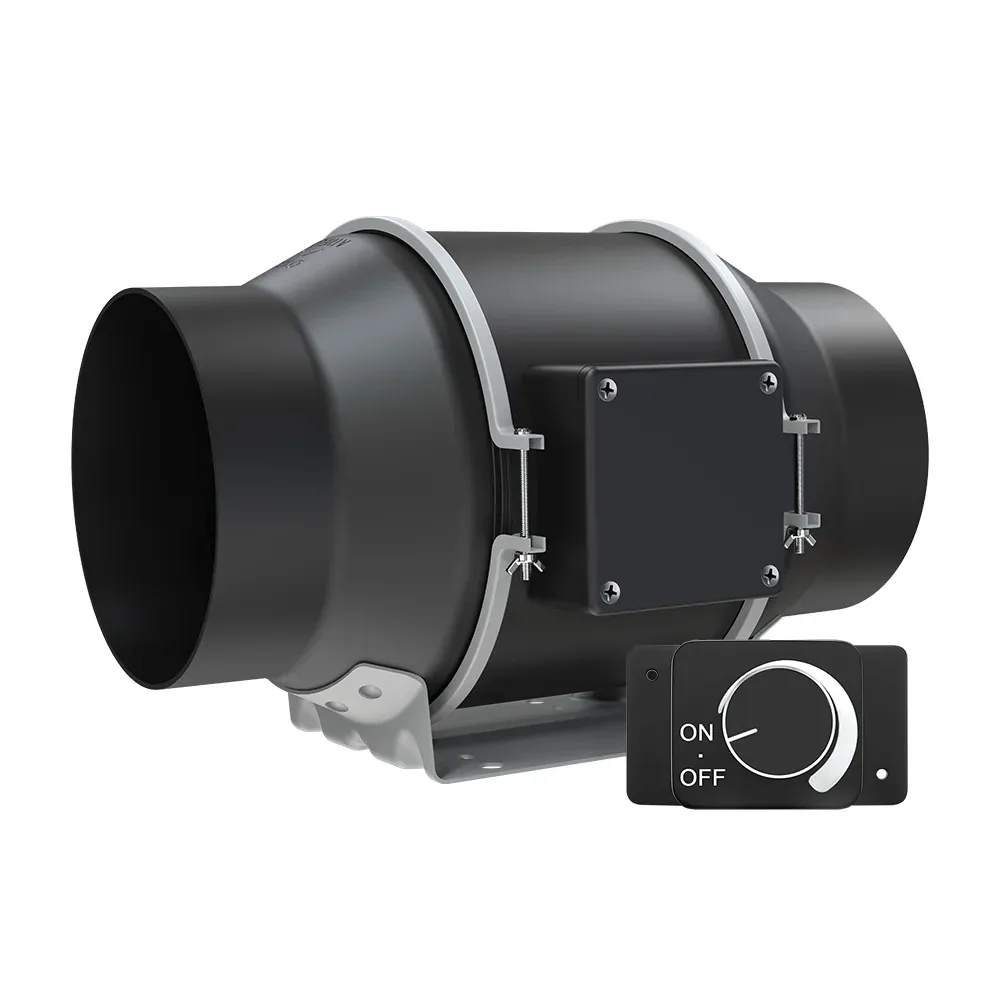
This guide uses one worked ratio, then shows how to turn that calculation into a defensible fan-selection decision. The figures are educational scaling estimates, not measured results for the LONGWELL product pictured below or a promise about any model.
The three fan-law equations at a glance
Let N be rotational speed, Q airflow, Δp fan pressure and P shaft power. Compare a new condition, subscript 2, with a known baseline, subscript 1:
- Q₂/Q₁ = N₂/N₁
- Δp₂/Δp₁ = (N₂/N₁)²
- P₂/P₁ ≈ (N₂/N₁)³
These equations assume the same fan geometry and comparable air conditions, with dynamically similar flow and no major change in efficiency. They scale corresponding points on a fan curve; they do not identify the installed operating point by themselves.
Worked example: reducing speed from 1500 to 1200 rpm
Start with the speed ratio: 1200 divided by 1500 equals 0.8. The airflow ratio is therefore 0.8, or 80 percent of the baseline value. The pressure ratio is 0.8 squared, which is 0.64. The shaft-power ratio is approximately 0.8 cubed, or 0.512.
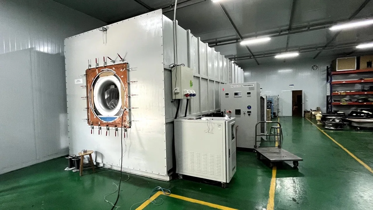
Put plainly, the calculation predicts 20 percent less airflow, 36 percent less pressure and roughly 48.8 percent less shaft power at corresponding curve points. Notice that no absolute airflow, pressure or electrical-input value has been invented. To produce those numbers, you need a controlled baseline curve and its test conditions.
A scaled fan curve is not the installed operating point
A fan in a duct system settles where its fan curve meets the system curve. Slowing the fan moves the fan curve; filters, coils, dampers and duct resistance still shape the other side of the intersection. A fixed pressure requirement can make the new duty point especially different from the simple free-air ratio.
After scaling, plot or calculate the new intersection. Then check it against the approved curve revision. This guide to reading centrifugal fan curves explains the curve axes and operating-point logic in more detail.
Why the cube law is not an electrical-input guarantee
The third equation is commonly shortened to “power follows the cube.” More precisely, it is an estimate for air power and, when efficiency remains similar, shaft power. The electrical input seen at the supply also reflects motor and controller efficiency, which can shift with speed and load.
For that reason, do not turn the 0.512 ratio into an energy-savings claim without measurements or controlled product data. The safe workflow is to estimate shaft power, compare the result with the verified absorbed-power curve, and confirm current, temperature and controller limits at the intended command point.
Speed increases deserve an overspeed check
The same equations work upward. At 110 percent speed, the airflow ratio is 1.10, the pressure ratio is 1.21, and the approximate shaft-power ratio is 1.331. A modest-looking 10 percent speed increase can therefore raise predicted shaft demand by about 33 percent.
A controller accepting a higher signal does not prove that the impeller, motor or assembly is approved for the resulting rpm. Before increasing speed, verify the mechanical speed limit, absorbed power, motor current, controller output, temperature and sound requirements. Treat a missing limit as an open engineering question, not as permission.
Where a real speed-controlled fan fits into the discussion
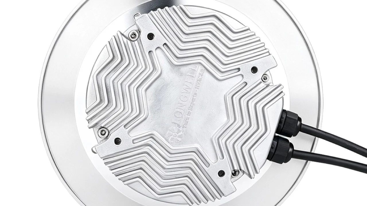
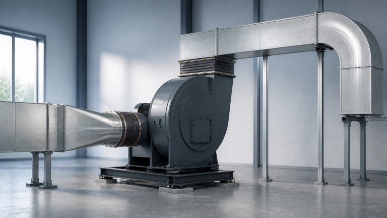
The photograph is a genuine LONGWELL LWDE3G100-IS-01 inline duct-fan image from the local product library. It confirms visible product form and the presence of a manual speed-control context only. It does not prove a duty point, control range, electrical rating, acoustic result, certification or current revision.
Projects that already require this architecture can browse the EC duct fan family. That route is for product discovery, not evidence that the pictured suffix fits a particular duct, controller or operating condition.
What to include in an RFQ after the calculation
A useful request for quotation begins with the decision conditions rather than a percentage-speed instruction. Provide the required airflow and static or total pressure, the operating air density or temperature and altitude, the available voltage, the control signal, the installation boundary and any sound or environmental limits.
Also identify the baseline curve revision, target speed range, predicted operating point, absorbed-power margin and acceptance test. The seven-step EC fan selection guide provides a broader specification checklist. Ask for the exact model suffix and revision on every returned drawing, curve and test record.
When not to rely on the simple ratios
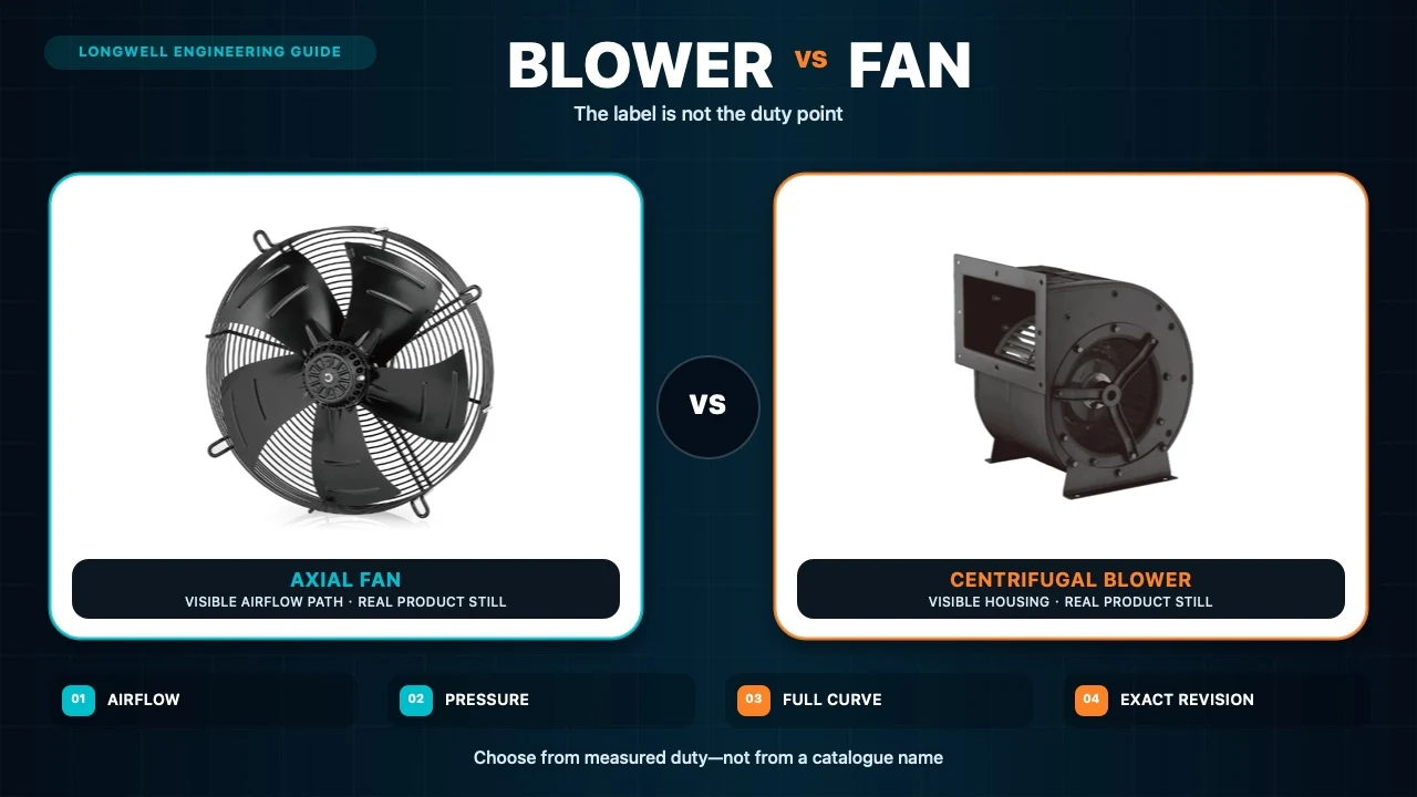
Recheck the method if fan geometry changes, air density changes materially, the operating point approaches stall, a controller imposes a limit, or efficiency shifts significantly. Diameter laws are a separate comparison for geometrically similar fans; they are not a shortcut for treating unrelated designs or suffixes as interchangeable.
Used within those boundaries, fan laws are excellent for screening a speed change. The calculation tells you what to expect. The revised fan curve, system intersection and controlled model evidence tell you what to release.