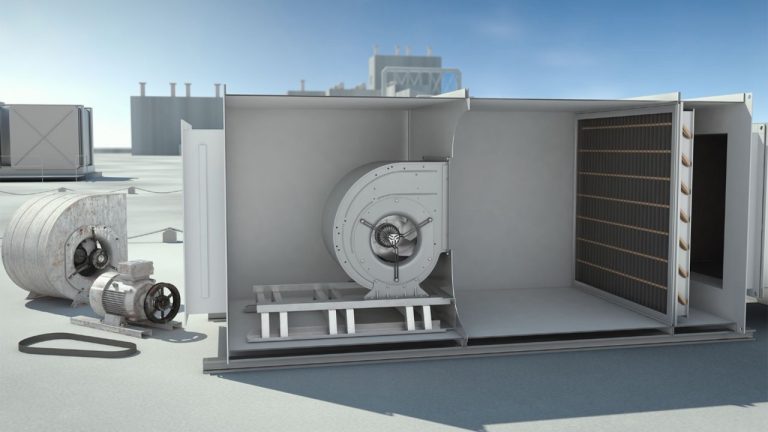
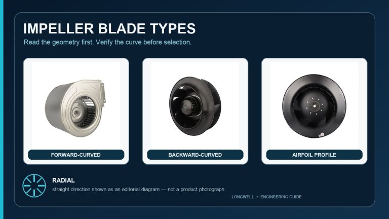
A fan wall, often called a FanGrid or fan array, is a group of smaller fans installed in one air-handling section and operated as one air-moving system. The fans usually share a plenum, frame, electrical distribution and control sequence. That definition is not enough to size or buy one.
The practical question is whether the complete array can meet required airflow and pressure in the real cabinet—during normal operation, part load and the declared fault case. The video introduces the layout. This guide adds the checks an AHU designer, retrofit engineer or buyer should put behind “FanGrid.”
What makes a fan wall different from several loose fans?
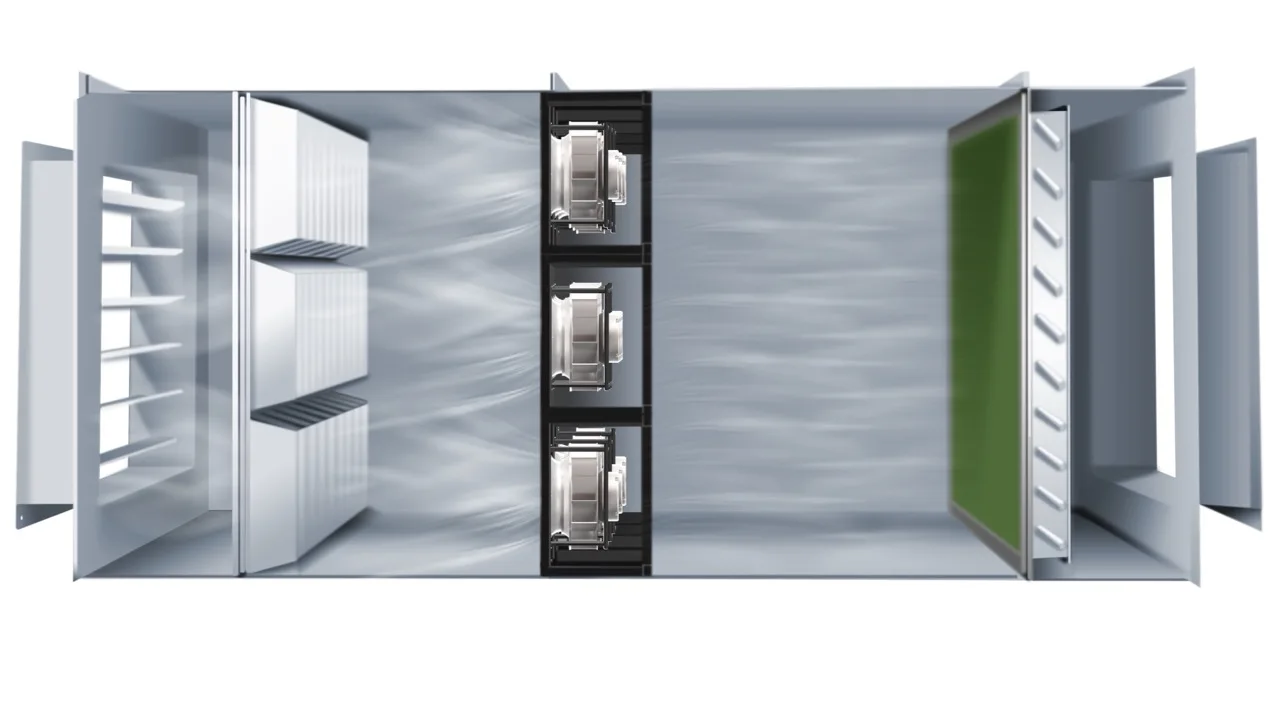
A true fan-wall design has a defined system boundary. Each cell includes a fan, motor, inlet and mounting position. The frame fixes their spacing. The plenum joins their air paths. Power and control hardware tell the cells when and how to run. The AHU casing, filters, coils, dampers and ducts create the resistance the array must overcome.
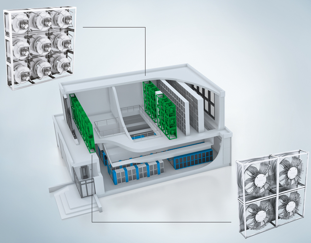
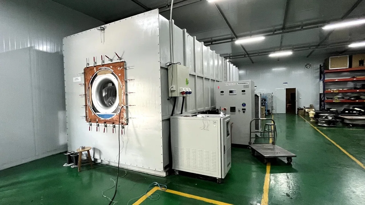
The image above is an explanatory Longwell application render, not a site photograph or an airflow simulation. It makes repeated cells and equipment placement visible. It does not prove capacity, velocity uniformity, efficiency, sound, redundancy or a customer result.
“FanGrid” is also used as a product or solution label, so its scope can vary between suppliers. Before comparing quotations, define what is included: fan modules only, modules plus frame, a wired control panel, a complete AHU section, or a commissioned retrofit.
Parallel fans add airflow at a common pressure
Fan-wall cells normally work in parallel. To build a parallel array curve, add the airflow contributions of the active fans at the same pressure. Do not add their pressure ratings, and do not multiply a free-air airflow number by the module count and call the result installed capacity.
The array curve then meets the equipment system curve. That intersection is the expected operating point. A filter change, coil revision, damper position, duct alteration or cabinet leakage can move the system curve. The fan count can stay unchanged while the delivered airflow changes.
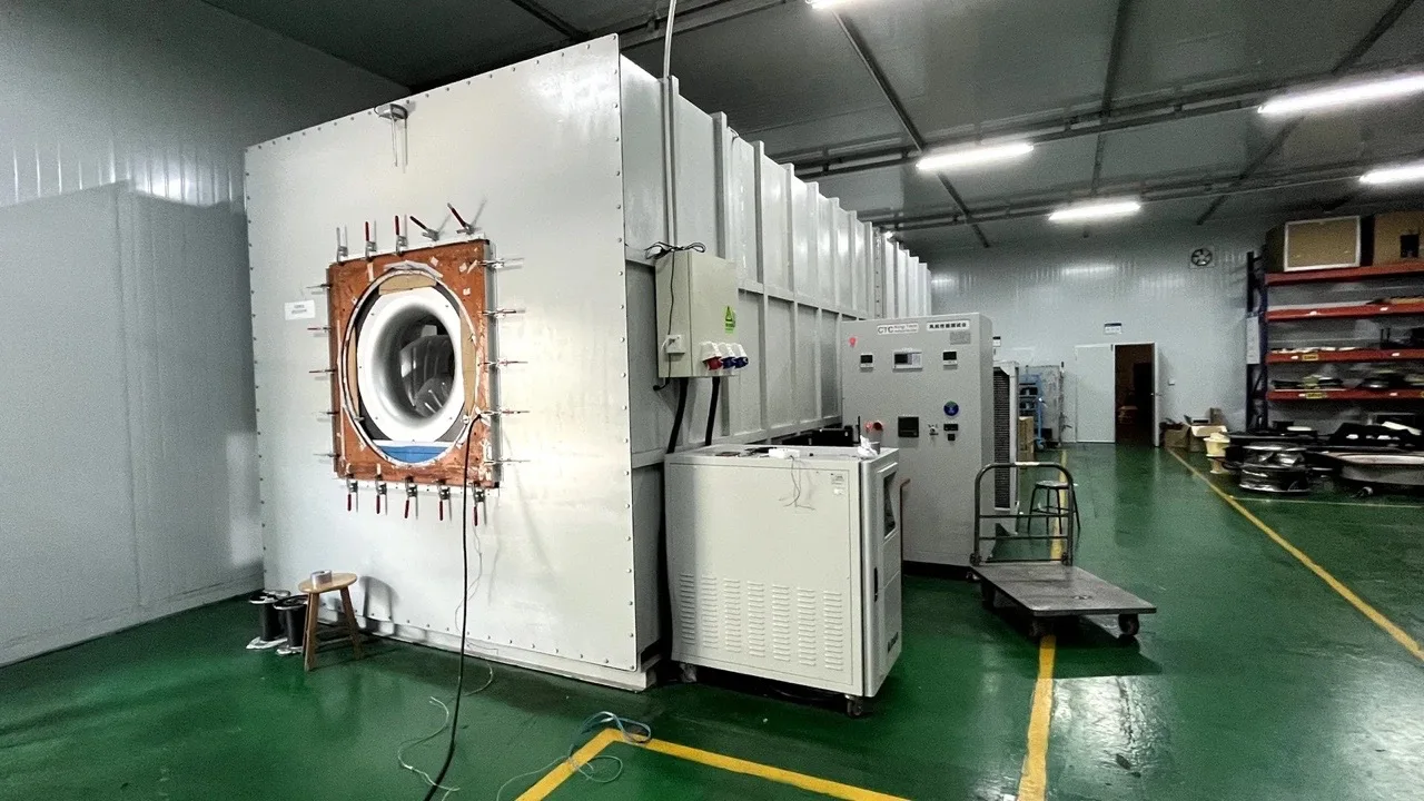
The U.S. Department of Energy fan-system sourcebook describes parallel operation and output loss when one fan is unavailable. ANSI/AMCA Standard 270 addresses aerodynamic testing of direct-drive fan arrays. These set a useful evidence boundary: request data for the proposed array and installation condition, not only an isolated-module curve.
The module photograph is not the array selection
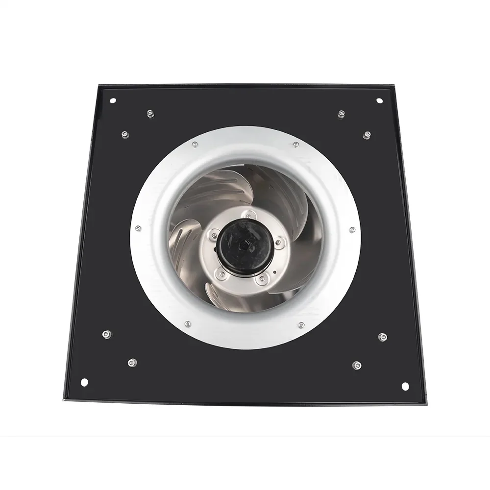
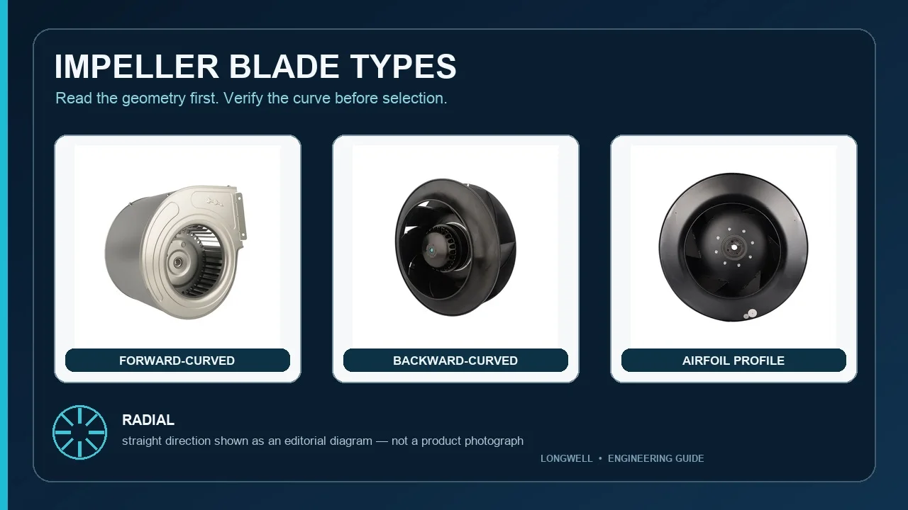
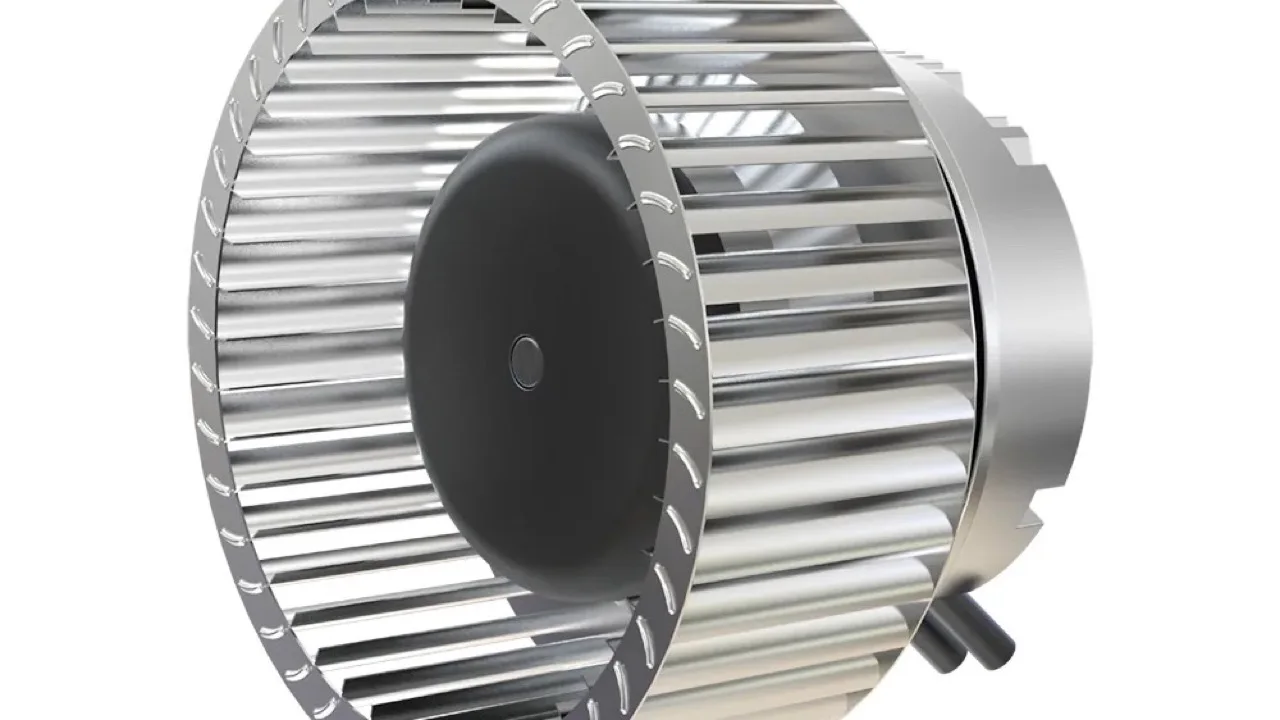
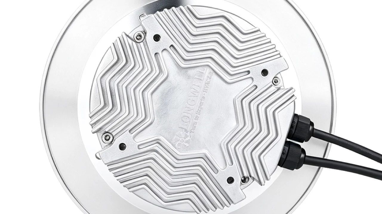
This is a real Longwell backward-curved direct-drive fan photograph from the authorized local product library. It shows the visible inlet, wheel and mounting plate of one representative plug-fan form. The same library image appears under more than one historical suffix, so it is deliberately not presented as exact-model proof.
Use the EC plug fan range for family-level discovery only. Release a cell for a project from its current full model and suffix, curve, drawing, wiring information, permitted speed range and revision—not from a family image or a diameter match.
Spacing and plenum geometry still matter
Distributing several inlets across an AHU section can support a more distributed flow path, but an even-looking grid does not guarantee an even velocity field. Cell spacing, partitions, inlet clearance, plenum depth, frame blockage, leakage and the distance to the next coil or filter can change how the array behaves.
Define the plane where uniformity matters and how it will be checked. Depending on the project, that may require an engineering model, a measured traverse or both. Keep the acceptance criterion, instrument method, operating state and measurement plane together; otherwise “uniform airflow” is not a testable requirement.
N+1 must survive the one-fan-off calculation
An extra cell is not automatically demonstrated N+1 capacity. With one fan unavailable, the active-array curve changes and the operating point moves. The remaining modules may need a different speed, and the idle opening may need isolation to prevent recirculation. Controller, motor and electrical limits still apply.
A reviewable N+1 claim states the critical airflow and pressure, identifies which cell is unavailable, supplies the one-fan-off array curve, defines the idle-cell treatment and shows the control response. If the reduced array only supports a lower-duty mode, call it graceful degradation rather than full-duty redundancy.
Controls determine what happens between design points
One sequence can modulate all available fans together. Another can stage cells and then vary the active-cell speed. Neither is universally better. The decision depends on the exact array curves, allowed speed range, system demand, acoustic boundary, electrical architecture and stable transition behavior.
- Command: document the speed or airflow command and its valid range.
- Feedback: state which speed, current, status, alarm or communications signals actually exist.
- Fault action: define detection, isolation, restart, remaining-cell command and the permitted reduced mode.
- Transitions: check startup, shutdown and staging without assuming that every cell responds identically.
- Ownership: identify whether the array panel, AHU controller or building system owns each part of the sequence.
A retrofit starts with the old cabinet, not a savings claim
For a fan-wall retrofit, measure the available section, access route, structural supports, inlet and discharge clearances, leakage paths and service space. Record the existing duty and its measurement basis. Confirm the available electrical supply, protection, cable routes, controls interface and shutdown constraints.
Then compare old and proposed systems at the same airflow, pressure definition, air density and equipment boundary. Include power and sound only when the test or calculation basis is declared. A new fan family, an EC motor or a smaller module count does not by itself prove a percentage saving or a payback period.
What to put in a fan-wall RFQ
- Duty: normal, minimum, maximum and critical-fault airflow and static or total pressure, with units and air condition.
- System boundary: filters, coils, dampers, plenums, ducts, leakage allowance and clean/dirty states.
- Array identity: full module model and suffix, quantity, frame layout, partitions, inlet clearances and exact document revisions.
- Curves: normal active-array curve, part-load states and the declared one-fan-off condition.
- Controls: command, feedback, alarm, communications, staging logic and responsibility split.
- Mechanical service: envelope, mass, mounting, guarding, isolation, access and removal path.
- Acceptance: where airflow, pressure, electrical input, sound and distribution will be checked, and by which method.
Longwell’s HVAC fan selection guide expands the duty-point workflow. For the purchase decision, ask the supplier to mark the proposed operating points on the current array evidence and list every assumption. That turns “What is a FanGrid?” into a specification an engineer can review and a buyer can compare.