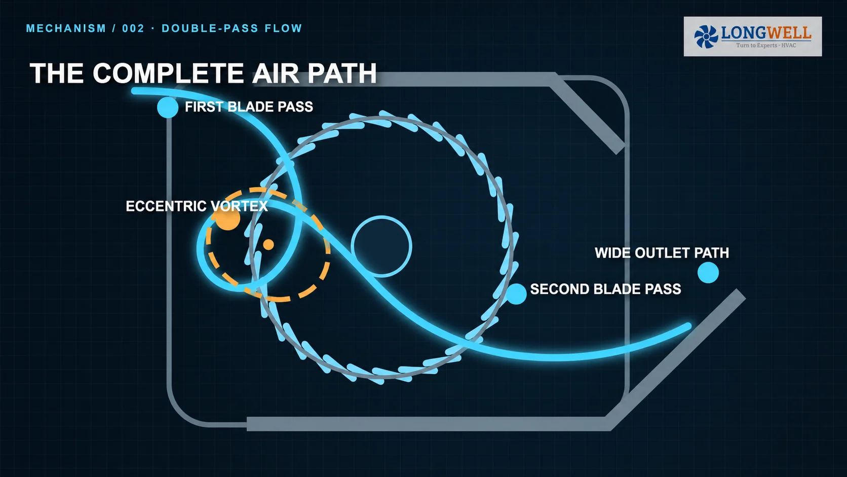
A cross-flow fan looks simple from the outside: a motor turns a long cylindrical wheel inside a narrow housing. Inside, air crosses the blade row once on the inlet side, turns around an off-centre vortex, and crosses the blades again before leaving through the outlet. That double pass is the core of the cross-flow—or tangential—fan principle.
The practical lesson is equally important. The wheel, casing and stabilizer form one aerodynamic assembly. A long impeller alone does not guarantee the airflow, pressure, sound level or outlet profile your equipment needs.
How air crosses the wheel twice
In an axial fan, air generally travels in the same direction as the shaft. In a compact centrifugal blower, it enters near the wheel centre and leaves radially. A cross-flow fan uses another route: its inlet and outlet extend along the wheel, while the main flow travels across the impeller.
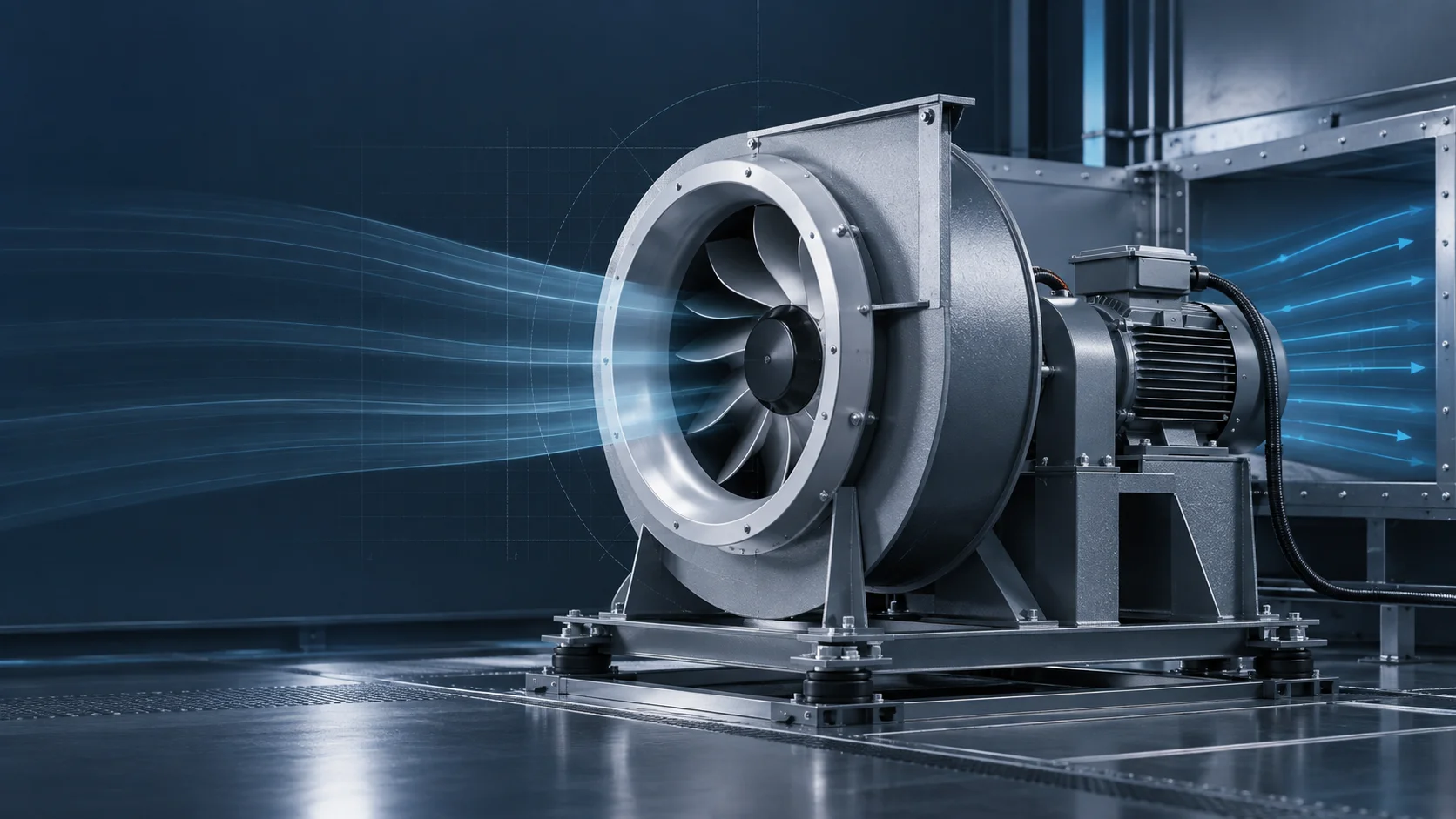
The inlet-side blades guide air inward. The flow turns through the wheel rather than leaving immediately, then meets the moving blade row again on the discharge side. The housing gathers this second pass into a broad outlet. “Double-pass fan” is a useful mental model, although the real flow remains three-dimensional.
The casing is part of the fan
A complete cross-flow fan normally combines a long bladed wheel, end supports, a drive motor, a shaped casing and a stabilizer or cutoff region close to the wheel. The casing is not simply a guard around a universal rotor. Its inlet admits the first blade pass, its contour helps organize the internal flow, and its outlet receives the second pass.
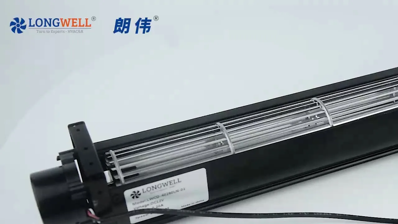
The real product image above shows the visible form of a LONGWELL LWCD-40290LN-01 assembly. It establishes appearance and architecture only. It does not prove a duty point, sound result, control method, certification, current revision or suitability for a particular machine.
Follow the three regions of the air path
First blade crossing: air approaches along much of the wheel length and passes through the forward-curved blades. Inlet clearance, screens and nearby panels can change what reaches this region.
Eccentric vortex: the dominant vortex sits away from the shaft centre. It helps divide the inlet and outlet portions of the impeller and steers flow toward the second crossing. Its position responds to the wheel, casing, stabilizer and operating condition together.
Second blade crossing: the flow passes through the moving blades again, then enters the outlet passage. What the connected equipment receives still depends on end effects, outlet resistance and nearby downstream geometry.
A wide outlet still needs an installed test
The stabilizer sits near the boundary between inlet and outlet flow. Moving it, changing the casing profile or opening a leakage path can shift the vortex. A fan may still rotate after such a change, but “it spins” is not evidence that it reaches the intended duty point.
Because the impeller extends across a long span, this architecture can support a broad discharge. It does not promise identical velocity from end to end. Motor-end effects, clearances, inlet blockage, screens, coils and outlet vanes can alter the distribution. Define the measurement plane and acceptance range, then test the complete installed assembly.
Choose cross-flow, axial or centrifugal by the air path
- Cross-flow: consider it when the equipment needs airflow along a long outlet and can accommodate the wheel, housing and end-mounted drive as one module.
- Axial: consider it when the preferred path is mainly parallel to the shaft and the system suits a circular or panel opening.
- Centrifugal: consider it when the inlet, outlet, package or resistance points toward a scroll-type blower arrangement.
These are layout distinctions, not a universal performance ranking. The LONGWELL cross-flow fan family includes several architectures. If a project specifically calls for a DC platform, the DC cross-flow fan range is a narrower browse path. That category page does not prove an exact model match.
Send an RFQ that can be answered without guessing
“I need a 40 mm cross-flow fan” is not enough for a safe selection. Give the supplier the operating condition and installation boundary:
- Full model and suffix from a clear nameplate photograph.
- Required airflow and static-pressure point, including where both are measured.
- Usable outlet length plus inlet, outlet and end clearances.
- Supply, control input, speed range and mounting orientation.
- Operating temperature, sound objective and expected duty cycle.
- Drawings of nearby filters, coils, grilles or panels.
- Required test method and acceptance rule for outlet distribution.
- The exact drawing, specification, test record and revision governing the proposed sample.
This guide to choose a cross-flow fan for an application provides a broader selection sequence. Model-specific statements must still be checked against controlled evidence for the exact suffix and revision.
Know what each piece of evidence can prove
A photograph can confirm visible construction and label identity. A controlled drawing can confirm the dimensions and interfaces shown on that revision. CAD can help check packaging and visible structure. None of them alone proves airflow, pressure, sound, life, certification or compatibility with another suffix.
A physical sample also needs an agreed test setup. Record the housing, inlet and outlet condition, voltage, control command, speed, instruments and measurement plane. Without that context, two different numbers may simply describe different tests.
The final purchasing question is therefore specific: which controlled complete assembly reaches the required duty point and outlet distribution inside the actual equipment? Ask for the answer against the exact suffix, revision and test condition.
Choose the right cross flow fan
Longwell manufactures 495 cross flow fans in-house. Send airflow, static pressure and voltage — an engineer replies with a matching model, performance curve and price within one working day.