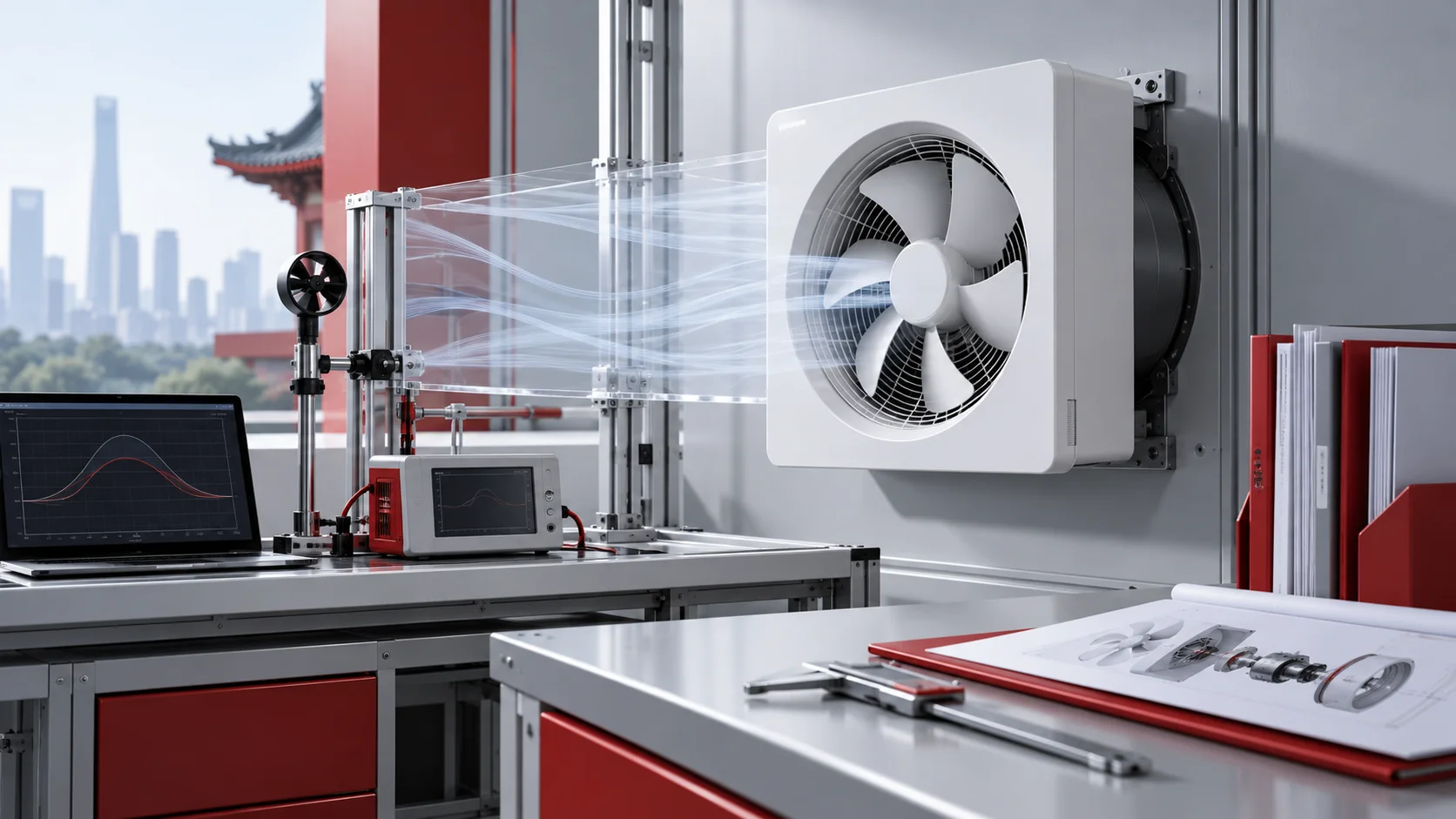
A centrifugal blower can be mechanically sound and still miss its duty because the connected ductwork presents disturbed flow that was not present during the rating test. An elbow at the inlet, an abrupt outlet transition, a damper in the wrong location, or duct weight on the casing can create a real installation loss. The result may look like a weak fan even though the problem is at the fan-system interface.
Correct centrifugal blower ducting is therefore not just a matter of making two flanges meet. The inlet must deliver usable flow to the wheel, the discharge needs room to develop, and every connector, support, transition, and accessory must fit the equipment-specific design. There is no single duct-length rule that is valid for every blower and operating point.
Start with the rated test condition and required duty
Before drawing the first transition, identify the fan arrangement, wheel type, rotation, discharge position, rated airflow, pressure, speed, gas properties, and the inlet and outlet conditions behind the published curve. The Longwell centrifugal fan family is a product-family starting point; it does not specify the exact duct connection for this installation.
Define the system duty at the expected density and operating condition, then reserve space for the duct geometry that lets the selected fan reach it. If the layout forces an immediate turn or severe transition, changing the fan arrangement may be better than accepting a permanent system-effect penalty. Our centrifugal fan selection guide gives the broader selection context.
Give the inlet uniform, low-swirl airflow
A centrifugal wheel responds poorly to air that arrives unevenly or already spinning. Keep elbows, partially closed dampers, walls, screens, and abrupt changes away from the inlet whenever the equipment instructions allow. Use a straight approach and a gradual, centered transition so the inlet cone is loaded as uniformly as practical. Avoid a flat transition plate that feeds one side of the wheel while starving the other.
When a nearby turn cannot be avoided, review elbow radius, turning vanes, straightening devices, rotation, and the manufacturer’s system-effect guidance as one geometry. Do not copy a diameter multiple from a different fan type and call it universal. The controlling distance is the value established for the actual blower, velocity, transition, and elbow arrangement.
Let discharge flow develop before it turns
Air leaving a centrifugal housing has a nonuniform velocity profile. A straight outlet section allows that profile to spread and recover static pressure before another fitting disturbs it. An elbow attached directly to the discharge, an abrupt expansion into a plenum, or a wall too close to a free outlet can add losses that were not included in the catalog rating.
Where space is tight, coordinate the blower’s rotation and discharge orientation with the first duct turn rather than treating the outlet as interchangeable. Use gradual transitions, avoid sudden area changes, and follow the equipment supplier’s effective-duct-length or system-effect method.
Use flexible connectors as controlled interfaces
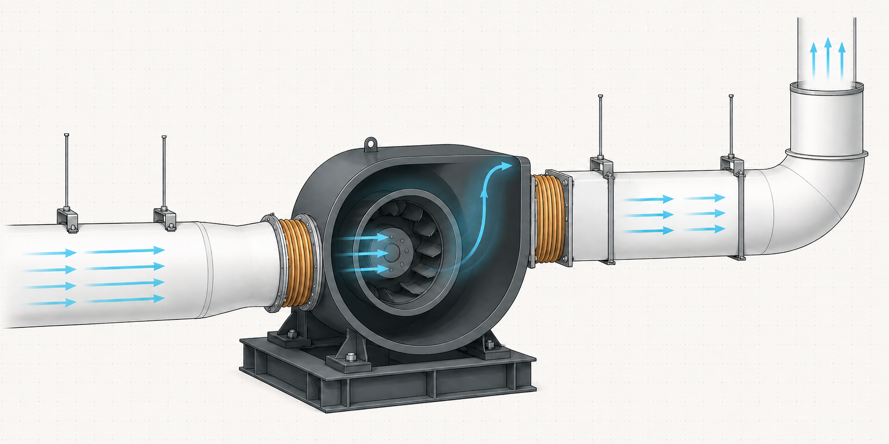
A flexible connector can reduce vibration transmission and accommodate limited thermal movement, but it cannot repair poor alignment or carry the duct. Align the fan and duct flanges before installing it. Keep the connector free of twist, sharp folds, excessive slack, stretching, or inward collapse. Select its fabric, coating, seam, flange, temperature, pressure, and gas-stream compatibility for the actual service.
On an isolated fan, the connector and any thrust restraints must allow the intended motion without becoming a rigid bypass. On a high-temperature system, expansion must be engineered rather than left to an underspecified fabric joint. Treat the manufacturer’s certified drawing and connector limits as controlling inputs.
Support ductwork independently of the blower
Ducts, stacks, silencers, and heavy fittings need their own supports. Their weight, thermal growth, or misalignment should not pull on the inlet cone, discharge flange, or housing. Excess loading can distort the casing, change clearances, disturb shaft alignment, or create contact with moving parts. A flexible connector does not make unsupported ductwork acceptable.
Place hangers and structural supports so installation loads are resolved before the final fan connection is made. Check support movement, expansion direction, access doors, drains, weather loads, and maintenance clearances. After every connection is complete, confirm that the fan base remains level and that the casing is not being forced into position by the duct.
Count every fitting and accessory in system resistance
The fan must operate against the whole system, not just straight-duct friction. Add the evaluated loss of elbows, transitions, branches, dampers, filters, coils, silencers, louvers, guards, flexible sections, and terminal devices. Nearby fittings may also impose a system-effect factor beyond their ordinary pressure-drop value because they interact with the fan inlet or outlet.
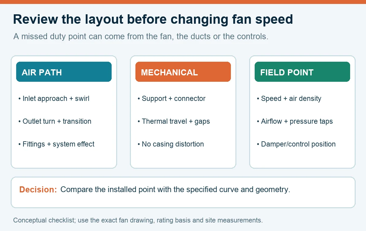
Document damper positions and control sequences at design flow. A damper that is fully open on paper but partially closed during commissioning changes both resistance and inlet conditions. When the predicted duty and field point differ, compare speed, density, airflow, pressure, and system configuration before increasing fan speed.
Commission the installed fan at the real operating point
Before startup, follow the equipment manual and site energy-control procedure. Confirm rotation by the approved method, restore guards, remove shipping restraints, inspect clearances, and verify that the inlet and outlet are free of loose material. Check flexible connectors, duct supports, fasteners, grounding, bearings, drive alignment, and access provisions from a safe condition.
At stable operation, record fan speed, airflow, inlet and outlet pressure at planned measurement locations, motor current, damper positions, vibration, and sound observations. Compare the measured point with the specified system and fan curve using consistent units and density corrections; our guide to centrifugal fan curves explains the relationship. Investigate unexpected pressure or vibration instead of masking it with speed.
Prepare a ducting review package before fabrication
- Fan data: arrangement, rotation, discharge, wheel, speed range, rated test condition, certified drawing, and service limits.
- System duty: airflow, pressure, density, temperature, gas composition, control states, and allowable operating range.
- Inlet geometry: straight approach, transition, elbow, damper, wall clearance, guard, and expected swirl or asymmetry.
- Outlet geometry: straight development section, transition, first turn, discharge condition, and calculated system effect.
- Mechanical interfaces: connector specification, independent supports, expansion, thrust restraint, drains, access, and maintenance envelope.
- Commissioning plan: pressure-tap locations, airflow method, speed, electrical readings, vibration checks, acceptance criteria, and responsible reviewer.
This package lets the fan supplier, duct designer, structural engineer, installer, and commissioning team review the same geometry before it becomes expensive sheet metal. It also separates an aerodynamic layout problem from a fan fault, a support problem, or a control problem.
Choose the right blower
Longwell manufactures 247 blowers in-house. Send airflow, static pressure and voltage — an engineer replies with a matching model, performance curve and price within one working day.