A fan can draw substantial power and still leave you unsure whether the energy is doing useful work. The right question is whether the installed system is delivering its required airflow and pressure at the condition being reviewed.
These three signs are screening signals, not diagnoses. Each should trigger a measured investigation. None alone proves wasted kilowatt-hours or justifies a setpoint, maintenance, or equipment change.
Define required duty before judging fan input
Record the airflow, pressure, ventilation, capture, cooling, pressurization, redundancy, safety mode, and schedule required for the operating state. High input is not waste when approved service requires it. Choose one acceptance point and one system boundary; a room average may hide weak delivery at a grille, hood, enclosure, coil, or equipment inlet. Longwell’s HVAC fan efficiency and system-design guide provides context for defining installed duty before interpreting input.
Sign 1: System resistance rises at matched airflow
A growing pressure drop across a filter, coil, silencer, damper, or duct section can make a controlled fan increase speed and input to hold the same airflow. In a fixed-speed arrangement, the same change may appear as reduced flow. The clue is meaningful only when operating mode and airflow are comparable.
Possible causes include fouling, obstruction, damage, a closed damper, leakage, a configuration change, or poor inlet and outlet conditions. Trace the full air path, including doors, flexible connections, transitions, guards, branches, grilles, and discharge clearance. The guide to improving airflow in ductwork is a system-side checklist, not proof that a particular restriction exists.
Confirm resistance growth without inventing a threshold
Trend component differential pressure with total airflow, fan speed, total system pressure, real electrical input, damper state, operating mode, and time. Check sensor zero, units, measurement planes, calibration, density basis, and uncertainty. Changed flow or a biased sensor can imitate resistance growth.
Compare like conditions. Do not invent a universal filter-replacement pressure drop: current manufacturer instructions, project limits, contamination risk, and required service govern the decision. Inspect only under the approved safe procedure.
Sign 2: Throttling or bypass persists during verified low demand
A fan may create pressure that the system then dissipates through a heavily throttled damper, open bypass, relief path, or opposing control action. Persistent high speed during genuinely low demand is another clue. But minimum outdoor air, process capture, pressure relationships, freeze protection, smoke modes, or simultaneous zone requests may require operation that looks excessive from one trend point.
Time-align demand and setpoint, command and actual speed, airflow, static pressure, critical damper positions, bypass or relief status, zone requests, alarms, schedule, operating mode, and real input. Review the sequence in plain language: which sensor creates demand, which device responds, which request can hold pressure high, and what happens during an override or fault. Do not lower a setpoint or shorten runtime without authorization, limits, monitoring, and rollback.
Sign 3: The supported operating point is outside the intended region
The installed operating point is where the fan characteristic and the system resistance characteristic meet. Oversizing, changed resistance, poor inlet or outlet geometry, wheel fouling or damage, leakage, or an incorrect configuration can move it away from the selected stable or efficient region. RPM, current, or free-air data cannot locate the point alone.
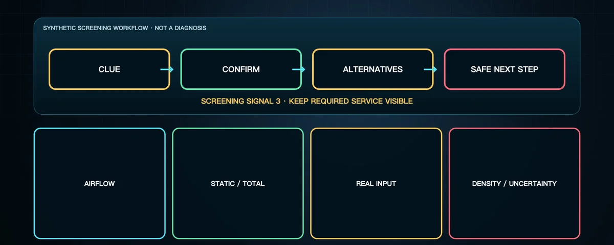
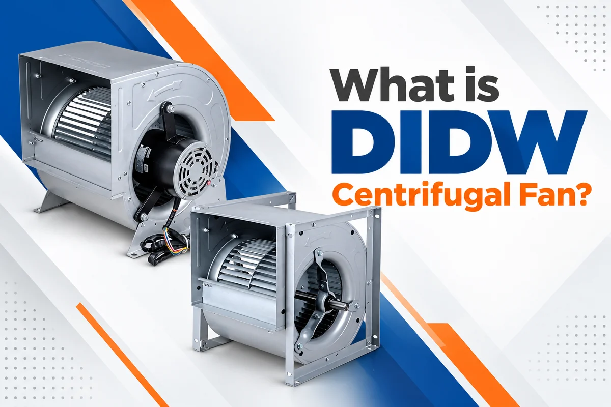
Use appropriate airflow, static or total pressure, real input, speed, air density, fan condition, and current manufacturer or certified curve evidence. Review transitions, obstructions, swirl, arrangement, and system effect. The guide to reading centrifugal fan curves explains the relationship, but applicable model data and installed measurements still control the assessment.
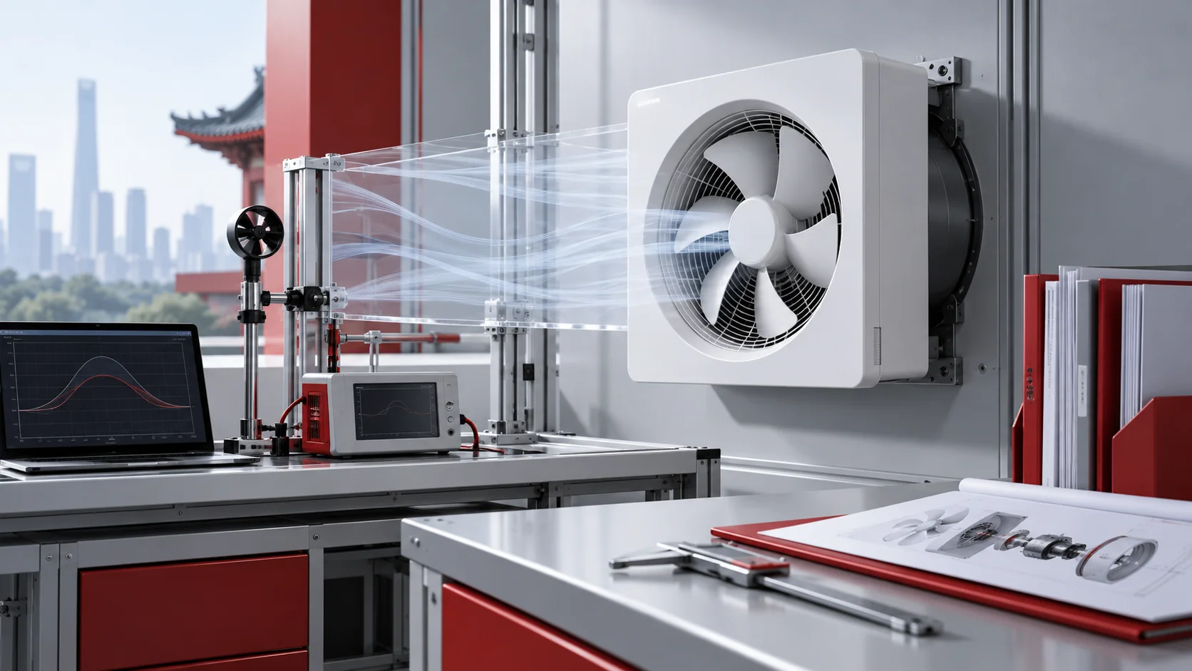
Build one synchronized measurement set
- Context: equipment mode, demand, setpoint, schedule, load, and safety state.
- Fan response: run state, command, speed feedback, alarms, overrides, and limits.
- Electrical input: total real input on a stated basis, obtained by qualified safe procedures.
- Air-side result: airflow plus applicable static or total pressure at documented planes.
- System state: filters, coils, dampers, bypasses, doors, branches, leakage, and obstructions.
- Process result: the temperature, pressure, extraction, cooling, or ventilation outcome being supported.
- Data quality: sensor zero, calibration, units, time alignment, density, averaging, and uncertainty.
Repeat the set at representative load states without changing several variables at once. Mark inferred values as inferred. A tidy dashboard is not a substitute for a defensible measurement basis.
Noise, heat, vibration, current, and dirt are clues—not proof
Tonal noise, turbulence, vibration, hot components, visible dirt, current, and RPM can guide an inspection. They may also reflect acoustics, bearings, motor or drive condition, load, installation, or a safety defect. None directly measures wasted energy. After a repair or cleaning changes the system curve, recheck limits, controls, airflow, pressure, and balance. Lower power is not success if required service is no longer met.
Choose the next action from the evidence
- Confirm required duty, the acceptance point, and operating mode.
- Validate sensors, instrument locations, method, and time alignment.
- Inspect the full air path and document its state.
- Capture airflow, pressure, real input, speed, controls, and process outcome together.
- Compare the supported point with the applicable fan curve and system resistance.
- Correct a clear maintenance, measurement, or control issue, then repeat the same measurement set.
- Only then evaluate a revised strategy, arrangement, or fan selection.
Screen fan technology only after the duty is defined
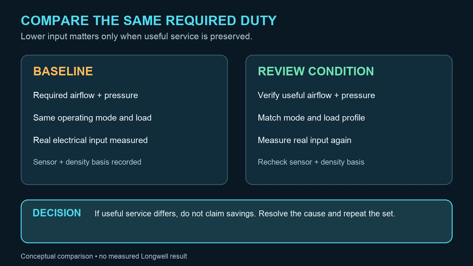
EC motors, VFDs, pressure reset, scheduling, staging, and system repairs are opportunities, not guaranteed savings. Compare alternatives at the same useful airflow and pressure across a representative load profile, including controls, standby losses, installation, commissioning, maintenance, tariff, and uncertainty.
If a backward-curved centrifugal arrangement is being considered, the EC backward-curved fan category is an initial screening path. It does not establish fit, compatibility, performance, or savings. Bring the required duty, load profile, air-path sketch, controls, electrical supply, installation geometry, and synchronized measurements to a project-specific review.