An EC FanGrid retrofit is not proven when the old fan disappears and the new array starts. It is proven when the retrofit delivers the required AHU duty and any claimed improvement is measured at an equivalent boundary. Airflow, pressure definition, air density, filter condition, operating mode, and electrical-input boundary must be comparable before “before and after” means anything.
This guide is for AHU manufacturers, owners, and design engineers preparing a retrofit and its acceptance plan. It makes no universal saving, redundancy, or payback claim. Those outcomes belong to the selected array, the installed system, the controls, and a documented project test.
Record a Baseline at More Than One Load Point
Survey the existing AHU while it is still operating. Record supply airflow, fan-section pressure rise, fan and motor input power, speed, damper position, filter pressure drop, coil condition, belt and sheave condition where applicable, vibration, sound, operating hours, and control sequence. Capture representative design, part-load, and minimum-flow conditions rather than relying on one full-speed snapshot.
Write down instrument identity, location, units, calibration status, sampling interval, and test timing. A slipping belt, blocked filter, abnormal damper position, or unresolved fault can inflate the baseline. Correcting such a defect may be valuable, but it should not automatically be credited as a permanent EC FanGrid benefit. The after-test must be able to reproduce the same measurement boundary.
Turn the Required Duty into an Acceptance Schedule
The old motor nameplate and fan diameter do not define the retrofit duty. Map the pressure losses through filters, coils, heat recovery, dampers, attenuators, casing, and ductwork using the project method. Check leakage, bypass, and non-uniform velocity at the coil face. Define whether the requirement uses fan static pressure, fan total pressure, or another documented project boundary.
Write the acceptance schedule before hardware selection. Include design, intermediate, and minimum airflow-pressure points; electrical-input limits; sound and vibration criteria; control response; service access; and environmental constraints. If availability matters, define the exact module-out state, remaining duty, permitted speed increase, power limit, and whether shared power and controls sit inside the failure boundary.
Engineer the FanGrid as Part of the AHU
Survey cabinet width, height, depth, access opening, coil distance, floor or rail capacity, lifting route, cable route, and removal clearance. Divide the face into modules without starving edge fans or leaving uncontrolled bypass paths. The support frame and blanking plates must seal the fan section while preserving safe module removal and maintenance access.
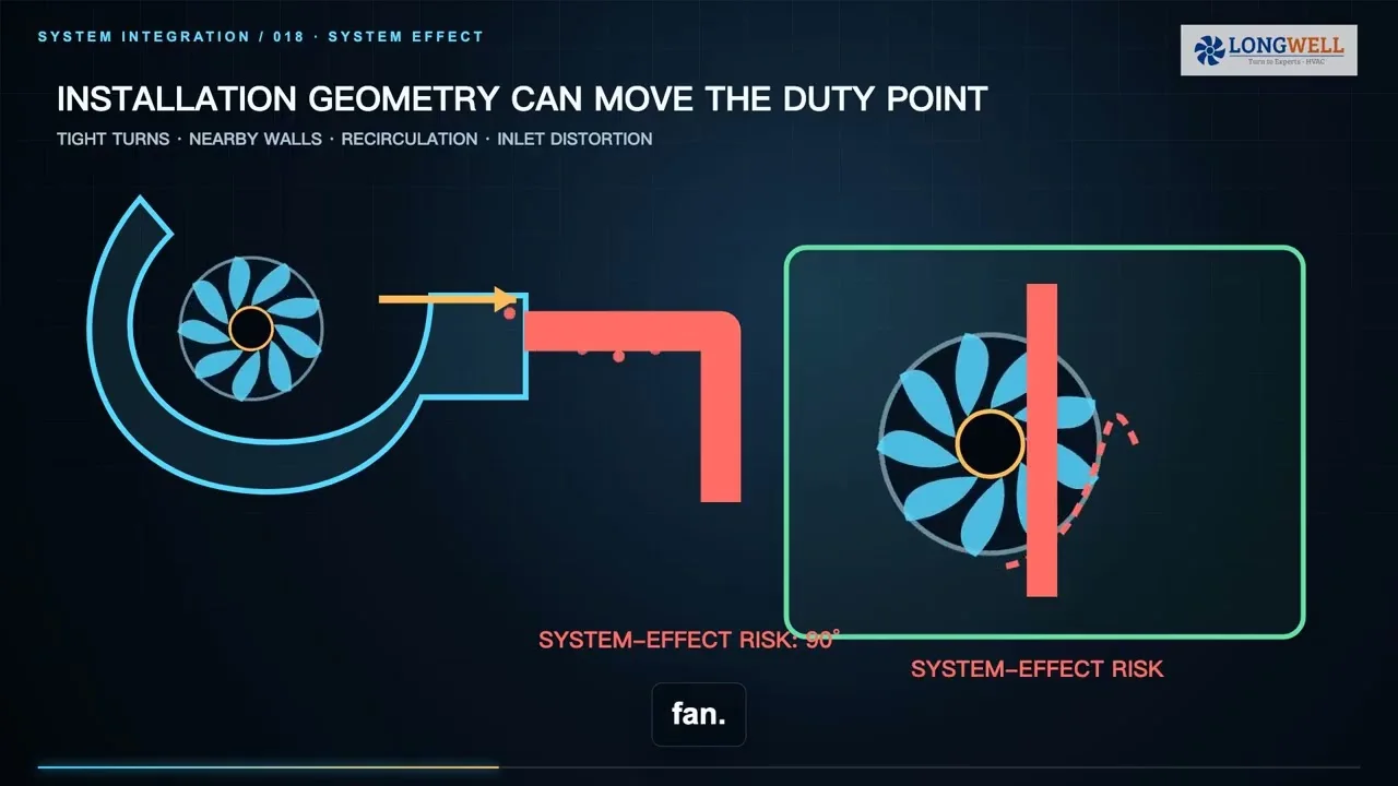
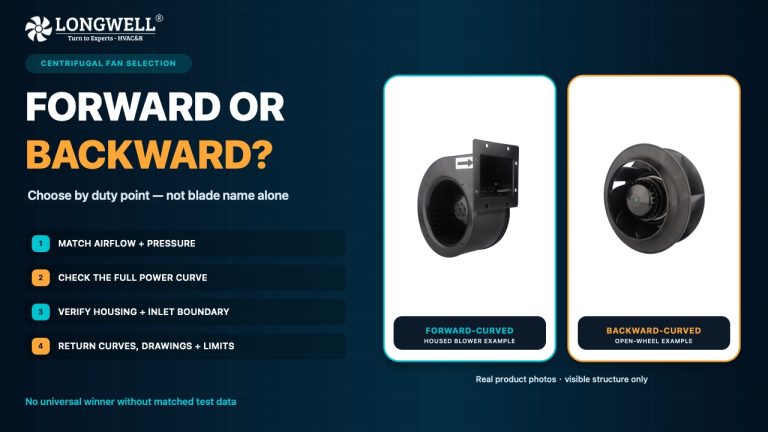
Select the array against the system curve for every required state. At a common pressure, the airflows of operating parallel fans combine, but installed performance can differ from a simple sum of catalog points. Partitions, inlet clearance, frame geometry, discharge mixing, and AHU resistance all matter. The Longwell EC plug-fan range is a product-family starting point, not a project selection or performance guarantee.
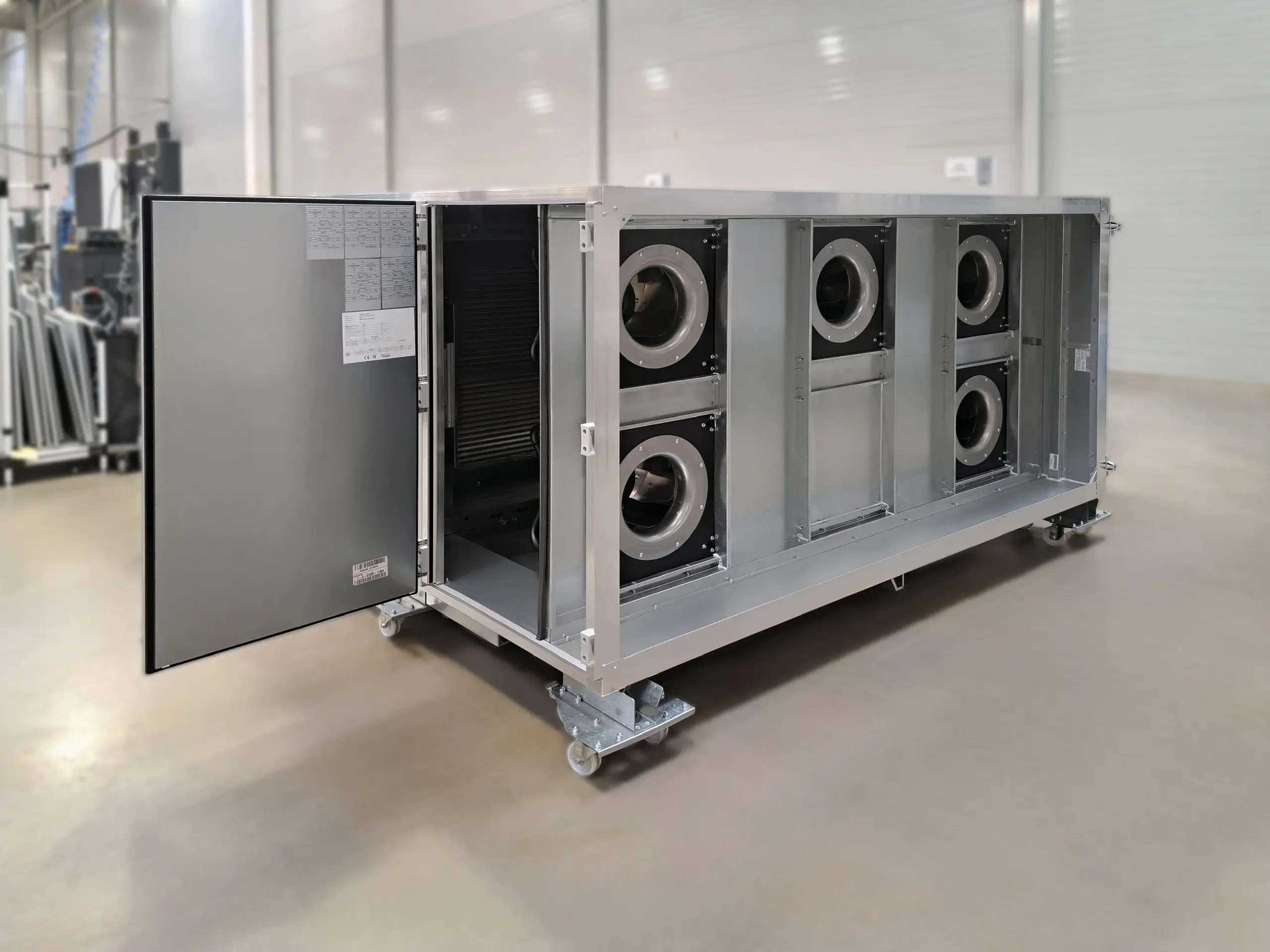
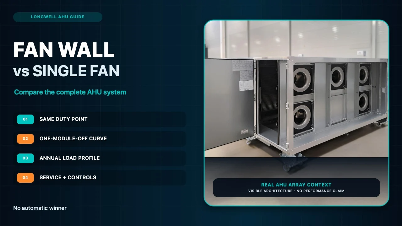
The photograph shows a real multi-fan arrangement inside an AHU section. It is application context only: it does not show the former fan, identify a customer, or prove airflow, power, sound, redundancy, savings, or payback. The AC-to-EC retrofit ROI guide shows how to structure the operating-hour and power-cost model; project curves, layout checks, measurements, and acceptance data still govern the retrofit.
The conversion needs a site-specific method statement. Qualified personnel must isolate the AHU, control hazardous energy, protect coils and casing, handle heavy rotating equipment and temporary structural conditions, install the engineered frame, close bypass openings, route protected power and controls, and restore guards. A catalog image cannot establish lifting, wiring, structural, or clearance requirements.
Commission Controls and the Defined Failure State
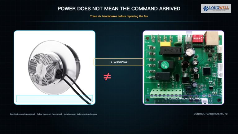
Verify the project-specific enable, speed command, feedback, alarms, communications, and fail-safe behavior before judging efficiency. Confirm that modules share load as intended and that a single fault does not create reverse flow, unstable pressure, or operation outside the remaining fans’ allowable envelope. Tune the airflow or pressure loop for stable response instead of copying the former drive frequency.
Trend command, speed, electrical input, feedback, and alarms through load changes. Test the defined module-out state and its recovery sequence. An efficient fan array with incorrect signal scaling, hidden alarm behavior, or unstable pressure control is not an accepted AHU retrofit.
Match Duty Before Comparing Power or Payback
Run the after-test at the same measurement boundary and under comparable operating conditions. Match airflow and pressure first, then compare electrical input. Recheck filter condition, damper position, air density, instrumentation, coil-face uniformity, sound, vibration, total array power, and the agreed module-out duty.
Build the annual business case from measured kilowatts and documented hours in each operating mode, adding applicable demand costs. Include verified changes in belts, bearings, filters, labor, modules, and downtime, then account for controls, installation, commissioning, and lifecycle costs. Keep sensitivity to run hours, electricity price, filter loading, and maintenance assumptions visible.
The handover pack should contain baseline data, the duty and acceptance schedule, fan and array curves, layout, structural and electrical details, the control sequence, commissioning results, the module-out test, the annual model, assumptions, and acceptance signatures. Another engineer should be able to reproduce both the technical decision and every claimed benefit.