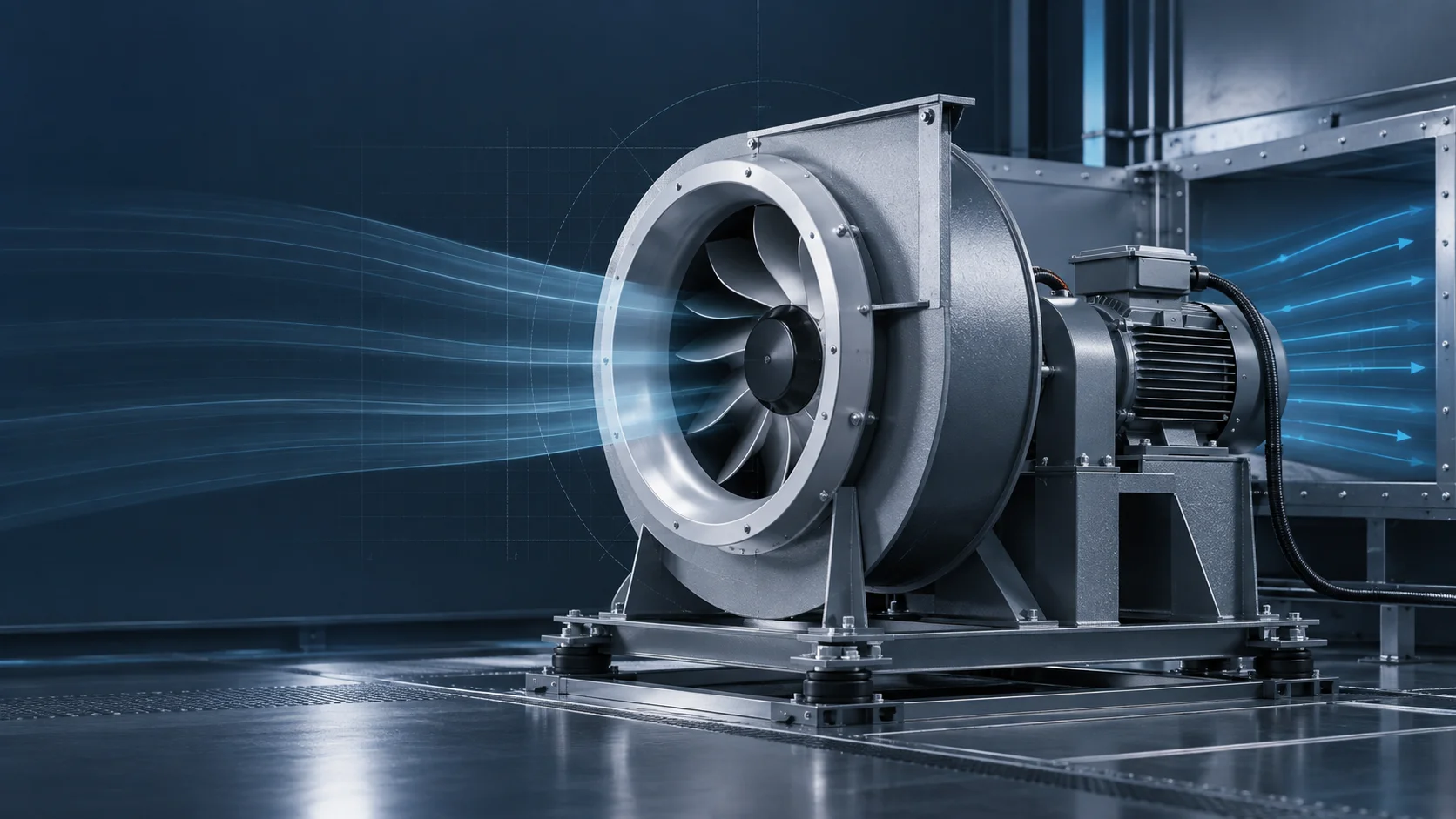
A plenum fan, also called a plug fan, is an unhoused centrifugal fan that discharges into an air-handling-unit (AHU) plenum. A housed fan guides the wheel discharge through a scroll or other outlet collector. The difference changes the air path and the installation boundary; it does not produce a universal efficiency, noise or size winner. If you are designing or replacing an AHU fan section, choose the architecture from the complete installed duty, geometry and evidence available for that unit.
The short video explains this choice. The two figures below turn it into an RFQ and commissioning check. They are conceptual engineering diagrams, not measurements from a particular LONGWELL fan or AHU.
Begin at the AHU, not at a fan label
AMCA defines a plenum or plug fan as a single-inlet impeller that pressurizes a plenum, while a housed fan includes a discharge collector in its fan rating. That distinction tells an engineer where the fan ends and the AHU begins. It does not tell you the motor technology, number of fans, drive type or control strategy. Those are separate choices. For an existing unit, record the design airflow, the pressure stations used for the duty, filter condition, coil and damper losses, available fan-section dimensions and the downstream component before requesting competing offers.
A plenum fan sends air from the wheel into the surrounding cabinet. The plenum then supplies the downstream section. A housed fan sends air through a defined outlet before that air enters the AHU path. Either arrangement can suffer when an inlet is blocked, a bend is too close, or a downstream face receives a poor velocity profile. AMCA’s system-effect discussion explains why a laboratory fan curve may not describe the same fan after installation.
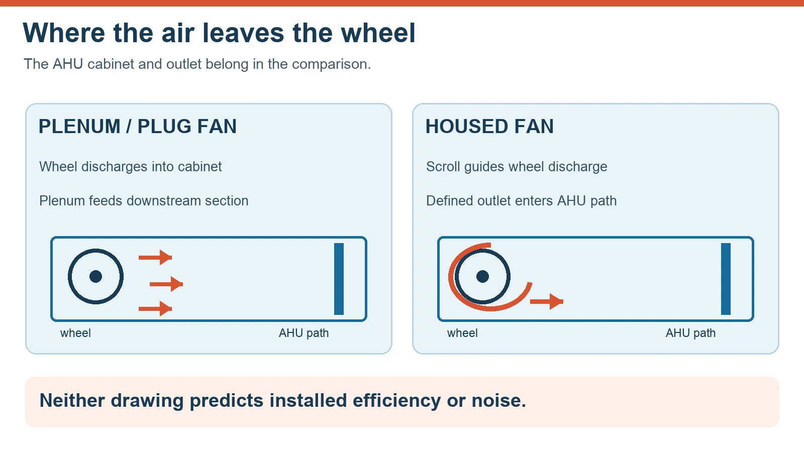
Compare pressure at the same measurement boundary
“Static pressure” printed on two quotations may refer to different inlet and outlet conditions. A scroll outlet, an AHU plenum and a downstream duct do not create interchangeable pressure stations. Ask each supplier to identify the fan rating basis, the AHU inlet and outlet stations, the proposed operating point and any allowance for system effects. Compare the complete fan-and-cabinet result at the same airflow and unit boundary. The total, static and velocity pressure guide is useful when reading the terminology, but it cannot replace a project-specific calculation.
Do not assume that removing a scroll costs a fixed percentage of pressure, or that one architecture always fits into a particular cabinet length. Recovery, mixing, losses and dimensions depend on the actual impeller, inlet, outlet and surrounding geometry. The correct next step is a coordinated AHU drawing and a curve for the exact proposed assembly, followed by a unit-level check where the installation makes the catalog boundary inadequate.
Use product evidence within its real scope
LONGWELL’s RLM plug-fan family page identifies a relevant plenum-fan family for an AHU discussion. An archived RLM500BAY-02 assembly drawing also shows a wheel, inlet ring, motor and mounting arrangement for that exact historical drawing. It is geometry evidence only here: its printed operating figures and dimensions are not being generalized to current RLM offers or to a particular AHU. Request the current model suffix, drawing revision, curve, motor and controller data before choosing a size or asserting fit.
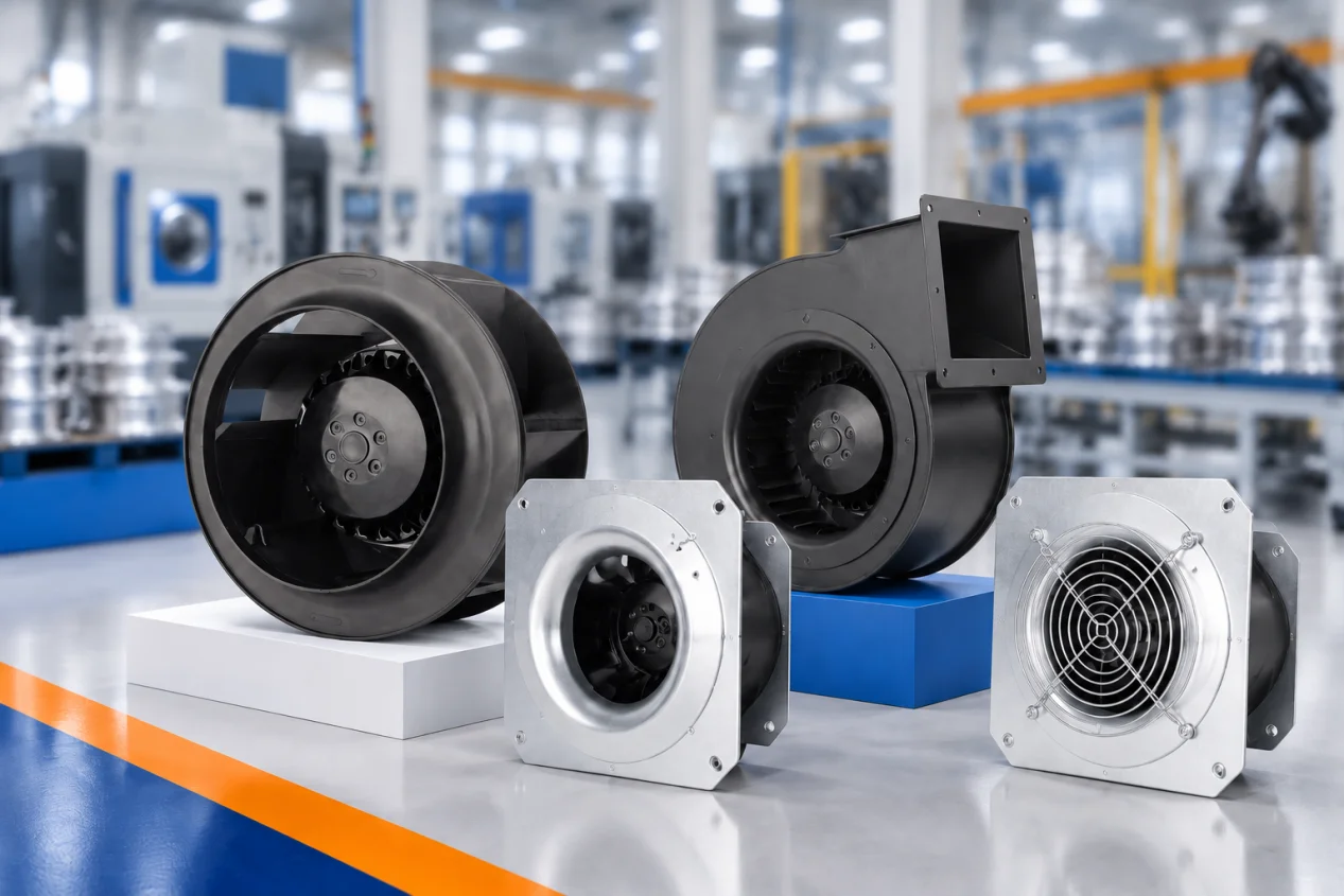
The airfoil centrifugal fan family provides another catalog route to discuss wheel and housing options. A family page identifies possible equipment; it does not prove interchangeability, certification scope, performance at your installed duty or savings against an existing fan. The same standard applies to a housed-fan proposal: require its complete assembly and rating basis rather than judging it from a catalog heading.
Check the plenum, outlet and downstream plane
For a plenum layout, identify wheel-to-wall clearances, inlet approach, the discharge space, leakage routes and the plane where airflow uniformity matters. A coil, filter or heat exchanger immediately downstream may need a distribution check rather than a single average flow number. For a housed layout, inspect the outlet transition and nearby ductwork. A sharp turn or obstruction may change the installed result even if the catalog fan curve looks strong. Draw the full section so both suppliers quote the same boundary and the AHU builder can reserve maintenance access.
If several fans share a plenum, add quantity, isolation and failure behavior to the drawing. An extra fan is not automatically N+1 capacity. Ask what happens at the required duty with one module unavailable, whether a stopped module permits reverse flow, how the remaining fans are controlled, and whether motors and controls stay within their limits. Verify any damper or isolation design for the actual array. These questions matter independently of whether the individual fans are direct drive or belt driven.
Judge power and sound at the required operating points
Compare electrical input at the same unit airflow and pressure, including the proposed motor and controls. If the AHU will operate at several flow rates, ask for those points and the control sequence rather than one headline efficiency value. For acoustics, request the relevant sound-power spectrum and the AHU attenuation path. A single overall decibel figure cannot describe every occupied-space or duct-noise outcome. Mounting, casing transmission and nearby flow disturbances can matter as much as the bare fan choice. Do not infer that either architecture is always quieter.
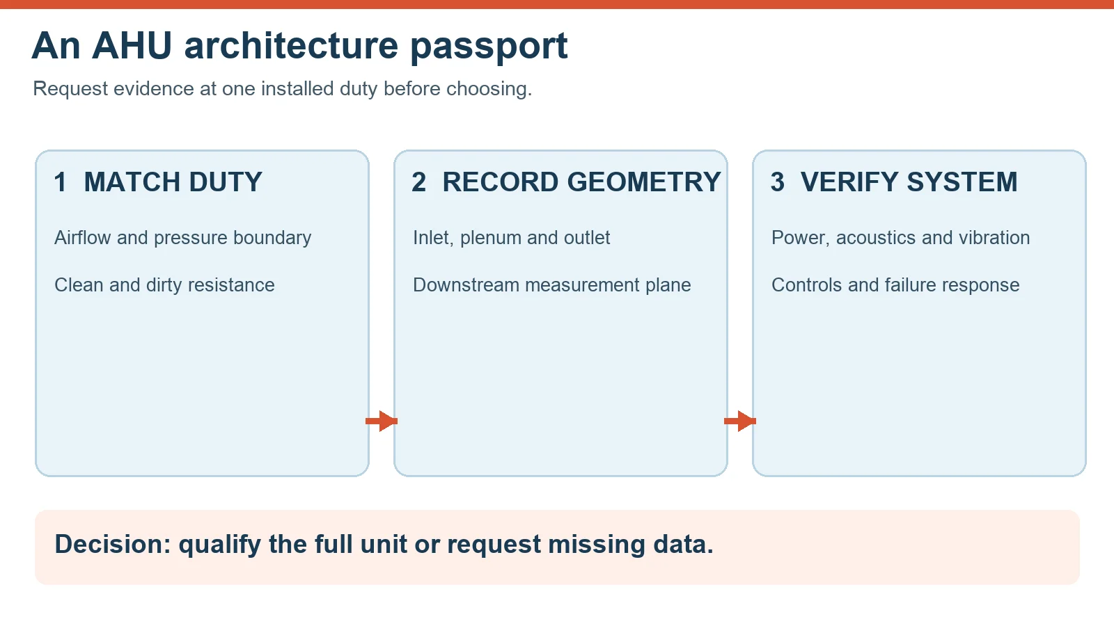
An RFQ and commissioning passport
Figure 2 groups the decision into three gates. First, match the duty: design airflow, pressure boundary, clean and dirty system resistance and any part-load operating points. Second, record geometry: exact wheel and assembly, inlet, plenum or scroll, outlet transition, casing leakage path, access and downstream measurement plane. Third, verify the system: curves, electrical input, octave-band acoustics, vibration, controls, array failure response and environmental or regulatory scope where applicable. Mark a field “data required” if no current document supports it.
During commissioning, measure or verify the quantities that were specified, at the agreed stations and operating modes. A model name or a good free-air curve is not an AHU acceptance result. Keep access doors closed during normal operation and follow the unit’s lockout and isolation procedure before inspecting a wheel or motor. The practical decision is to qualify the exact installed assembly with the required evidence, or hold the choice until the missing boundary or test is supplied.
Choose the right ec plug fan for ahu replacement
Longwell manufactures 83 ec plug fan for ahu replacements in-house. Send airflow, static pressure and voltage — an engineer replies with a matching model, performance curve and price within one working day.