A fan wall controller has to make a recurring decision: should the running fans change speed, or should the array change how many fans are active? Treating that choice as a single pressure threshold misses the real control problem. The sequence must connect a valid system measurement to demand, fan availability, active fan count, speed commands and verified response.
The practical aim is not to copy a generic sequence. It is to build a project-specific control path that remains understandable during normal modulation, transitions and faults. The discussion below explains the engineering checks that support that decision without prescribing universal setpoints, timing values or controller settings.
Define the controlled result before writing stage logic
Begin by stating what the fan wall is expected to control. Depending on the air system, the relevant variable may be pressure, airflow or another approved system condition. Those are not interchangeable. A sensor in a plenum can see a different disturbance pattern from one in a downstream duct or a critical room, so its location becomes part of the control definition.
Document the measurement point, units, operating modes and acceptance criteria for the installation. Identify whether demand comes from a local loop, supervisory system or coordinated equipment sequence. This prevents the stage manager from reacting to a signal whose physical meaning is unclear.
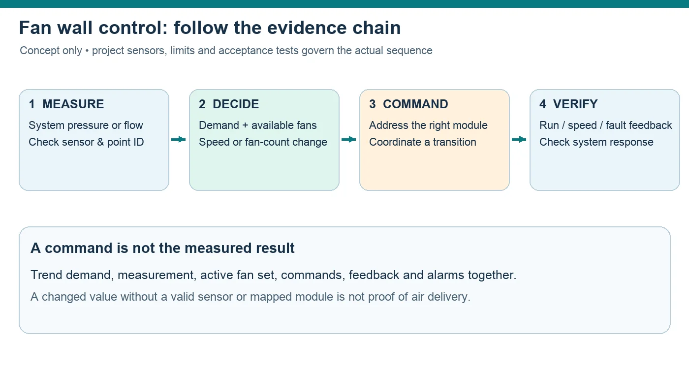
Prove sensor quality and point identity first
Staging cannot correct a biased, unstable or incorrectly mapped measurement. Check sensor installation, calibration status, tubing or impulse-path condition where applicable, and the way signal failure is represented. Compare the control value with an independent commissioning measurement under an approved test plan rather than assuming that a plausible display is accurate.
Point-to-point verification matters just as much. Each enable command, speed command, run indication, speed feedback and fault state must belong to the intended module. A swapped address can make a healthy fan look unresponsive while the wrong fan changes state.
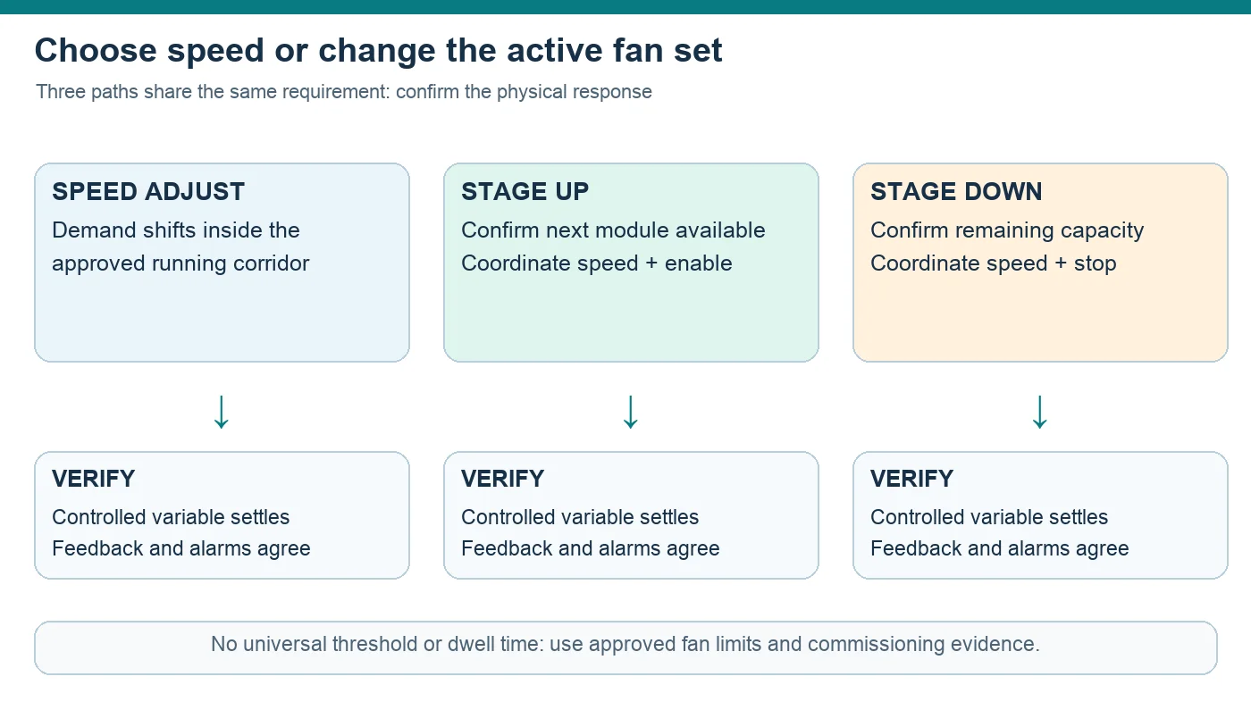
Choose speed correction or a fan-count change deliberately
When demand moves, the running fans can often respond through speed control within their approved operating range. A stage change becomes a separate decision because enabling or disabling a module changes the active flow area and the way the common system load is shared. The controller should therefore evaluate system demand, available modules and the permitted operating region together.
The guide to reading fan performance curves provides useful background for relating airflow, pressure and the operating point. The applicable fan data and measured array behavior are still required for a real project. A general curve cannot establish a staging threshold, safe speed range or expected array result.
Coordinate each transition instead of issuing an isolated start
Adding an active fan while every running module holds its previous command can disturb the controlled variable. Removing one without preparing the remaining modules can cause the opposite response. A usable sequence defines the transition as a coordinated state change: confirm availability, prepare commands, change the active set, then verify that the system settles in the intended state.
Separate stage-up and stage-down conditions and include appropriate persistence so that measurement noise or a small load reversal does not repeatedly cycle the array. The required separation, dwell behavior, ramping and minimum operating constraints are project-specific. They should come from the approved equipment limits and commissioning evidence, not from a percentage or delay copied from another site.
Check the physical fan wall behind the control diagram
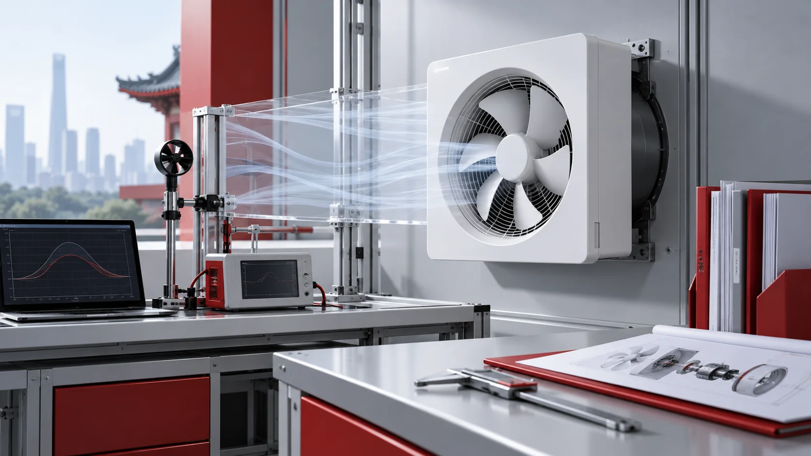
A control sequence acts on real modules that share an inlet, discharge region and surrounding equipment. The image below shows a multi-module centrifugal fan arrangement and cable routing as general fan-wall context. It does not identify a specific model, controller, site installation or performance level.
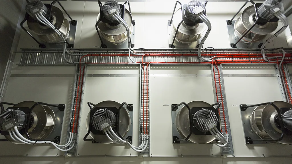
This physical context is important when a module is stopped. Depending on the actual design, an inactive opening may interact with the common pressure field, and a rotor may move even though its software command is off. Isolation or backdraft provisions, guarding, stored energy and the authorized service procedure must be reviewed separately from normal control logic.
The related centrifugal fan wall overview is a useful navigation point for the application concept. Treat its system language as context only; project layout, failure behavior and operating limits still need their own engineering review.
Use feedback to prove that a command became a result
An enable command proves only that the controller requested a state. Speed feedback provides another observation, but equal speed or equal current does not prove equal airflow contribution across every module. Local resistance, geometry, contamination and module condition can produce uneven behavior even when commands look consistent.
Trend the control chain as a synchronized record: demand, controlled measurement, active fan set, command, actual response, equipment condition and alarms. This helps distinguish a sensor problem, mapping error, slow physical response and unstable control decision.
Commission normal, degraded and recovery states
A commissioning plan should test normal modulation and planned stage changes, then address approved abnormal states such as an unavailable module, invalid sensor signal or lost feedback. Each state needs a deterministic response, a visible alarm path and a defined return-to-normal process. The safest degraded state depends on the facility and cannot be declared universally.
Critical-system tests require authorization, monitoring, abort conditions and rollback. Do not improvise faults in a live environment for tuning; use an approved test environment, simulation or controlled commissioning window.
Turn the sequence into a useful engineering enquiry
For supplier or controls review, provide the system objective, measurement locations, intended operating modes, available fan data, point list, state diagram and the required response to unavailable equipment. Include the proposed stage logic as a sequence of conditions, commands, confirmations and recovery actions. Mark every value that still requires project testing.
For family-level product research, the EC backward-curved centrifugal fan range offers a starting point. It is not an assertion that a listed fan fits a particular wall, control architecture or duty. Selection still requires the applicable drawings, operating data, electrical details and system verification.
A sound fan wall sequence is therefore traceable from measurement to decision to physical response. When that chain is documented and tested, operators can see why the array changed state and engineers can revise the project logic without relying on hidden assumptions.