A room is positive or negative only relative to a named neighbouring space. That relationship tells you the preferred direction of air through an opening. It does not, by itself, tell you whether the room has enough outdoor air, captures a source, or meets a sector-specific requirement. Start with the boundary and the purpose of controlling it; choose the fan only after the air paths are known.
First name the pressure reference
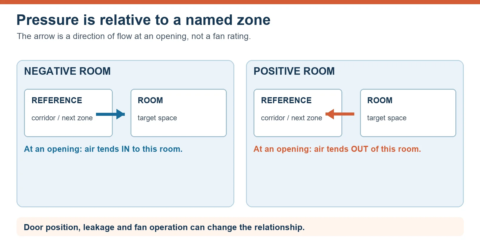
Imagine a workshop and the corridor beside it. If the workshop is held at a lower pressure than that corridor, air tends to enter the workshop through a gap. If it is held higher, air tends to leave through the gap. The words “positive” and “negative” have no useful meaning until you state which room compared with which other zone. A room can even sit between two zones in a pressure cascade, with a different relationship on each side.
Air follows the available openings. Door positions, ceiling voids and penetrations can create unintended routes. A drawing that labels one room “negative” is therefore a design intention, not proof that every opening carries air in the planned direction. The diagram below is a conceptual boundary check, not a project pressure specification.
Choose the objective before choosing the sign
For a source that should be contained, the design may call for air to move from the adjacent zone toward the source zone, followed by a controlled exhaust route. For a room that needs protection from adjacent air, the design may call for clean, conditioned supply and outward flow at the selected boundary. These are different objectives, and both still require the correct supply, exhaust, filtration and discharge arrangements for the process.
A kitchen extract system, a dusty workstation, a clean production area and a healthcare isolation room do not share a universal pressure value. The contaminant, applicable standard, enclosure leakage, door use and failure response all change the design. In healthcare, for example, the CDC’s directional-airflow guidance describes clean-to-less-clean flow; project-specific clinical rules still govern the installation. Treat any simple “positive for clean, negative for dirty” phrase as a starting objective, not as a released design.
Keep four measurements separate
Room differential pressure compares two spaces across a defined boundary. Supply and exhaust airflow describe how much air travels through the intended paths. Fan static or total pressure describes the fan’s duty against resistance in its own air circuit. Local capture velocity describes air motion at a hood or source. A value from one of these categories cannot simply stand in for another.
More exhaust than supply can tend to pull a room negative, but the resulting differential depends on leakage area and operating state. A closed door may show one result while an open loading door shows another. A clogged filter or changed fan control can move the balance again. The pressure sensor location and reference tube route also matter. Record what each instrument measured, where, and with which equipment running; avoid copying a generic airflow offset or pascal value from an unrelated application.
Match the fan to the air circuit
The fan selection question is the installed airflow at the resistance of the duct, filters, grilles and other components. A maximum airflow number and a maximum pressure number from a catalogue are not a simultaneous operating point. The exact fan curve and system resistance must meet at the required duty; then the controls and voltage must fit the project. LONGWELL’s inline duct fan family is one candidate route for a ducted supply or exhaust path. The family page identifies choices; it does not establish that a particular model can maintain a given room pressure or meet a safety standard.
For the selection method, see LONGWELL’s fan-curve guide. The 2026 company catalogue also lists medium-pressure blower series with fan flow and pressure data, which are fan performance fields rather than measured room differentials. If the air path contains a high-resistance filter or a changing control state, request the exact model revision and curve before treating any series as suitable. A fan running at its rated speed does not prove the intended inter-room airflow direction.
Build a pressure-control passport
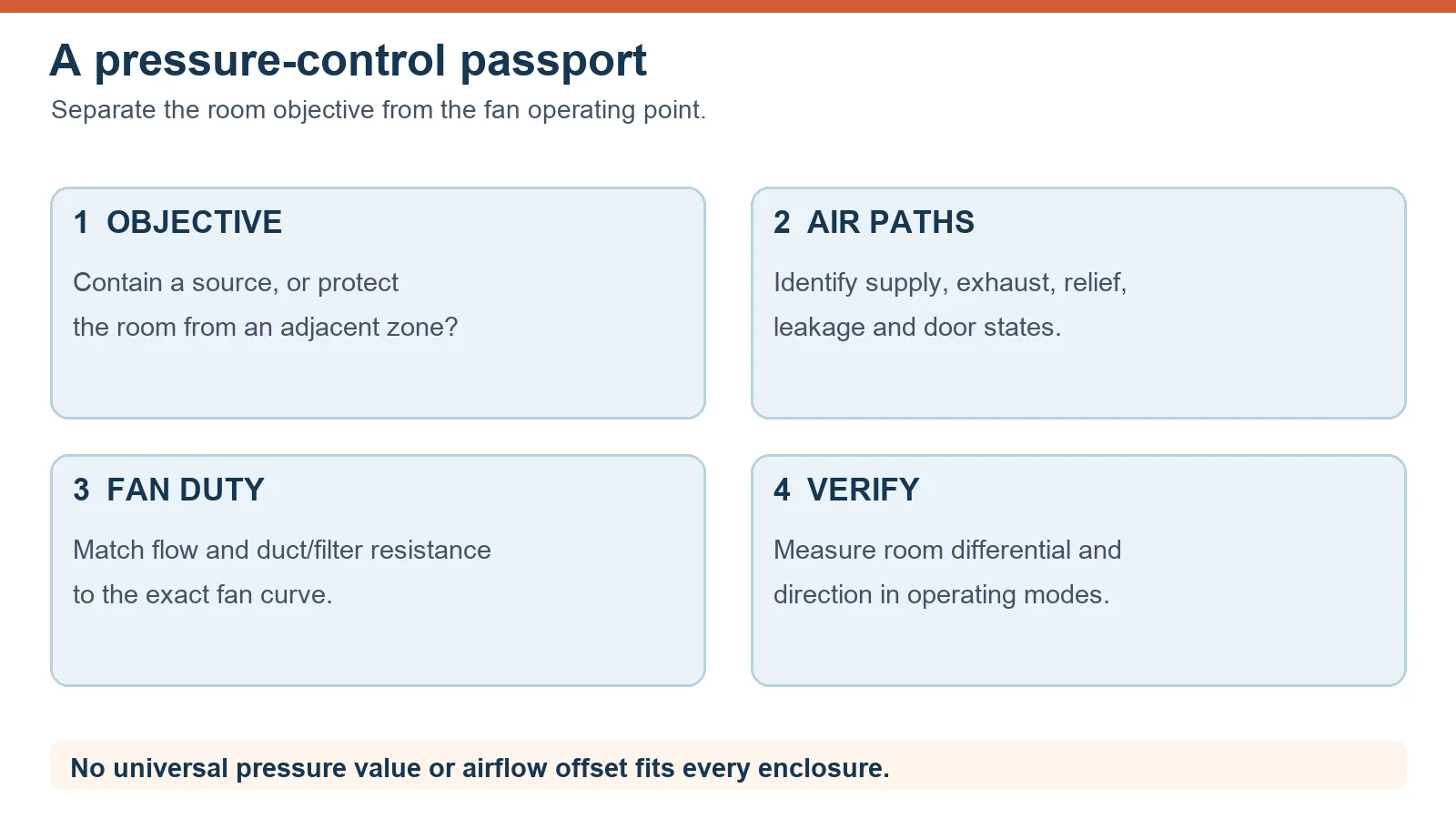
Put the objective, reference zones and room boundaries in one brief. Mark outdoor-air intake, supply, source exhaust, relief and return paths on a single diagram. Record the expected states of doors, dampers and filters. For each fan, attach the selected curve and the duty point with the resistance basis. For the room, define where the differential and airflow direction will be checked. These are related records, but they answer different questions.
Commissioning should include representative occupied and process modes, a door state that matters to the application, and the response to an alarm or fan failure. Keep the acceptance limit in the applicable project standard and signed design, not in a generic blog article. Figure 2 provides a compact order for the evidence. It is a checklist, not a measured result.
What to send for a LONGWELL review
Send the intended airflow direction and the two zones involved, a sketch of the air path, target airflow at the fan, the estimated duct and filter resistance, electrical supply, control signal, ambient conditions and the operating modes to verify. Share the applicable process or local standard separately. LONGWELL can then assess a fan candidate against its own curve; the system designer must still confirm the complete room and its commissioning result. If the application is safety-critical, include the qualified specialist responsible for the design and release.
Need a fan candidate for a defined air path? Send the duty point and boundary sketch to sales@longwellfans.com.