An EC fan array is more than several fans operating in parallel. If a pressure sensor cannot observe changes in IT airflow, or multiple control loops chase conflicting targets, the modules may speed up and slow down while rack-inlet conditions continue to deteriorate. A credible data center design connects load, airflow path, sensing, shared control, module feedback, energy measurement, and failure testing.
This engineering framework is intended for data center operators and MEP consultants. The reviewed static Longwell images establish visible product structure only; they do not prove a named installation, project duty, redundancy, saving, or payback. Installed claims must come from selected fan curves, project controls, calibrated measurements, and matched system tests at the actual site.
Write the Cooling Requirement Before Selecting Fans
Start with the IT-load profile, acceptable rack-inlet conditions, actual supply and return airflow path, pressure-control objective, and number of active modules. Define peak and part-load states, expected changes in rack population, containment, recirculation, bypass, filter condition, and any operating modes that change room resistance.
The physical fan module can establish dimensions, inlet clearance, outlet arrangement, mounting, and service access. It cannot prove installed airflow, pressure, energy use, or redundancy. Those outcomes depend on the selected performance curves and the complete system curve, including array partitions, inlet conditions, downstream resistance, air density, and installation effects. The Longwell EC plug-fan family is a discovery route, not a project selection or suitability claim.
Put Sensors Where They Observe the Real Load
Measure temperature where the IT equipment receives air, not only at a convenient cooling-unit location. Place the pressure sensor where changes in equipment airflow and system resistance are visible to the control loop. A stable pressure reading has little value if the selected point is isolated from the rack condition the system is meant to protect.
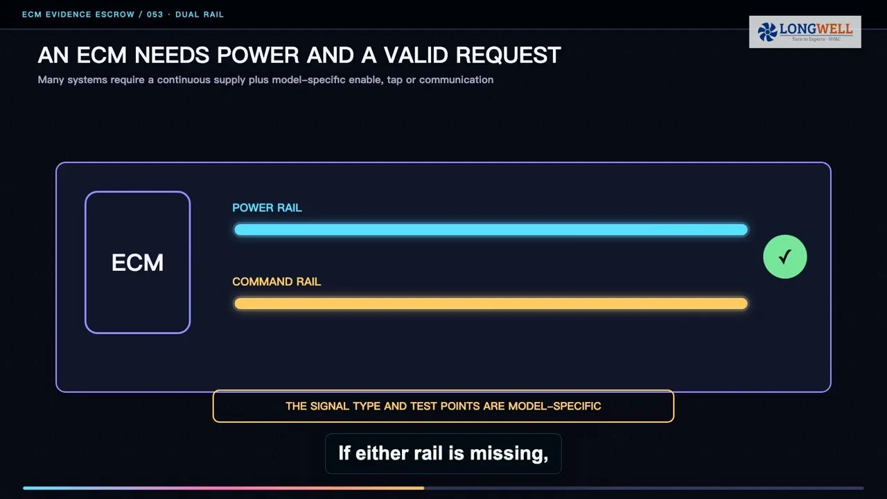
Use one coherent demand strategy. A master controller can distribute a common speed request to active modules and validate the result at rack inlets. Independent trims should not be allowed to fight unless the final control design explicitly coordinates them. The lowest available command is not automatically the best operating point; airflow must remain stable, sensing must retain authority, and every monitored rack inlet must remain within the project boundary.
Lock the Electrical and Control Interface
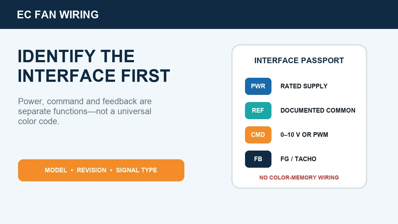
Document the exact supply, command, reference, feedback, alarm, and communication functions for the selected fan and controller. One Longwell example specifies a 230 V supply, a 0–10 V or PWM speed command, and an FG speed-feedback output. It does not specify serial communication. That example cannot be generalized into a pinout or a promise of current, temperature, alarm, or network telemetry.
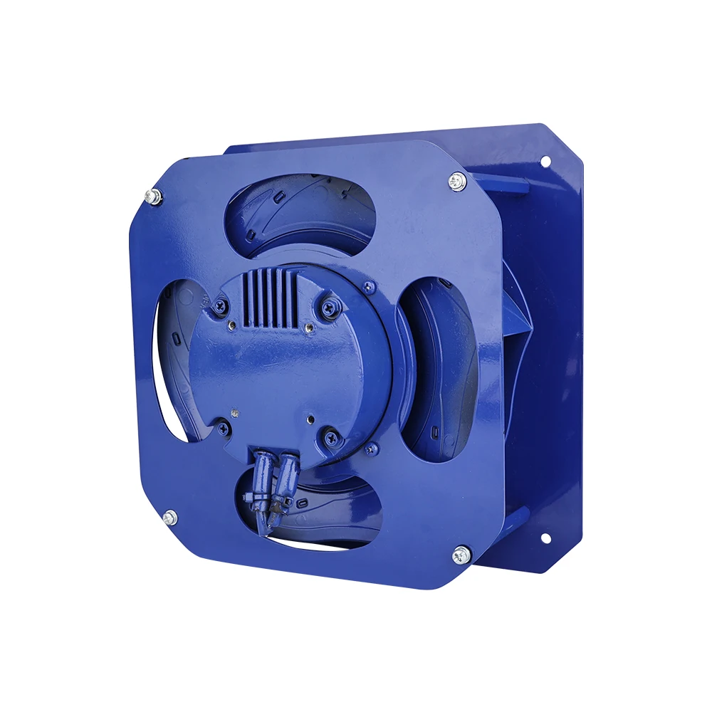
The photograph shows the controller side of the exact named LWBE3G190-072PS-02 static product asset. It establishes visible structure only; it does not prove an array duty, control sequence, performance, certification, data-center installation, or customer result.
Send a deliberate command to each active module and compare requested speed with actual feedback. Persistent mismatch may indicate wiring, configuration, obstruction, or a module fault. Define the available evidence points before procurement: command, speed feedback, externally measured current where provided, controller status, rack-inlet temperature, and pressure trend. Availability varies by fan and project.
Measure Part-Load Performance and Test One Module Off
For the same air system, fan power changes approximately with the cube of speed, so speed reduction can reduce electrical input significantly. The cube law is a useful first check, not a guaranteed saving. System resistance, air density, control behavior, installation effects, and fan efficiency still influence actual power. Use the fan-curve operating-point guide to keep airflow, pressure type, speed, power, density, and revision aligned, then trend measured electrical input at the real duty points.
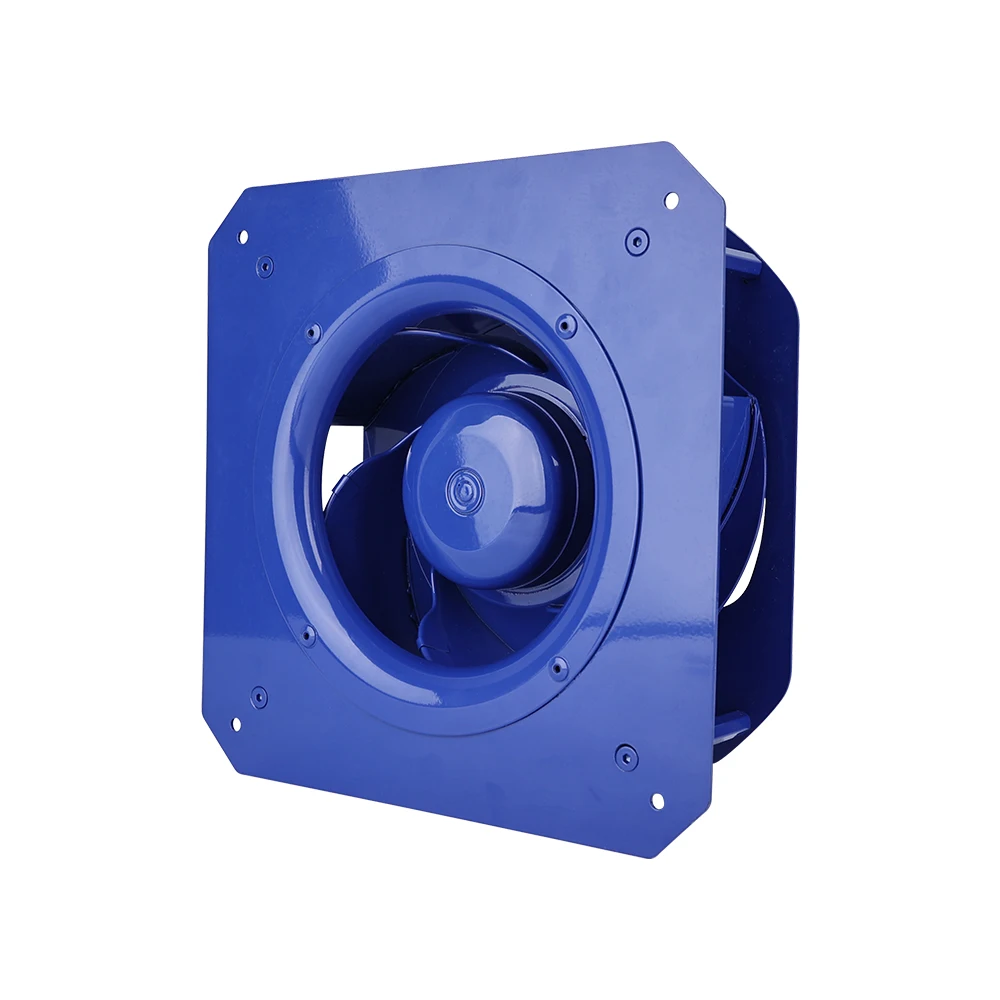
The inlet-side photograph identifies the same product variant and its visible mounting form only. It is not an installed array curve, a pressure rating for this article, or proof that the module suits any data-center duty.
When one module is isolated, the array has a new operating point. Recalculate and verify the remaining modules’ speed, current, and position on their allowable curves. Confirm shared control pressure and use the rack-inlet trend as a safety boundary while inspecting the response. Check reverse-flow or isolation behavior and ensure that recovery does not create unstable pressure. This control test establishes whether the remaining modules obey the intended sequence; it does not release system redundancy. Describe the design as N+1 only after the separate approved server-inlet failure scenario has passed its exact duty, environment, and limits.
There is no universal minimum speed, pressure setpoint, deadband, ramp rate, fault timeout, or energy-saving percentage. These settings must be tuned to the room dynamics, sensor authority, selected fans, control architecture, and risk criteria.
Replay the Load Schedule and Release Traceable Evidence
Before handover, replay the project’s representative load schedule from low to full demand, then perform the control portion of the approved one-module-off scenario. Trend rack-inlet temperatures, pressure, fan command, actual speed, electrical input, controller status, and alarms. Stop at the project safety boundary. Verify filtering, deadband, ramp limits, integral action, restart order, and fault handling. This sequence does not replace the system-level thermal redundancy record.
Document sensor locations and calibration, airflow boundaries, selected curves, array layout, control sequence, normal and failure-state measurements, and all acceptance limits. A smooth control graph is not sufficient if rack inlets are outside the specified envelope, and an acceptable inlet temperature does not by itself prove efficient fan operation.
The completed evidence package should let another engineer reproduce the decision and distinguish product capability from project performance. That is the basis for a defensible data center EC fan array: coordinated control, visible module response, measured part-load behavior, and verified recovery from the exact failure state used to define redundancy.
Choose the right ec fan
Longwell manufactures 34 ec fans in-house. Send airflow, static pressure and voltage — an engineer replies with a matching model, performance curve and price within one working day.