A fan does not pass commissioning because its drive type looks familiar. Direct-drive and belt-drive packages have different service points, but both must prove the scheduled airflow and pressure at a declared air density and installation boundary. The useful comparison is therefore the evidence each package needs before handover—not a generic claim that one architecture always wins.
This checklist starts where a general architecture comparison ends: when a buyer, installer or service team must decide whether the actual fan, motor, controls and transmission are ready to accept.
Lock the duty and submittal before inspecting hardware
Write down airflow, static or total pressure, air density, temperature, fan speed, electrical supply and the exact pressure boundary used for acceptance. Identify the fan model and suffix, wheel, motor, controller or VFD, and the revision of every curve and instruction. A catalogue family name is not enough; nearby suffixes can have different motors, limits or service parts.
Then reconcile the submittal with the delivered assembly. Confirm rotation, discharge orientation, base and isolation arrangement, flexible connections, clearances, access panels, wiring diagram, guarding and the permitted speed range. If a field change affects sheaves, wheel speed, motor settings, controls or inlet conditions, return to the responsible selection authority before testing. Do not “correct” a mismatch by increasing speed until the assembly limits and revised duty are documented.
For direct drive, inspect the whole motor-wheel package
A direct-drive inspection is not simply “no belts to check.” Verify how the wheel is coupled or mounted, shaft or rotor retention, wheel-to-inlet clearance, free rotation, fasteners, motor cooling path, cable strain relief, grounding and service access. Confirm that the control signal, minimum and maximum command, rotation logic and fault behavior belong to the exact motor/controller combination.
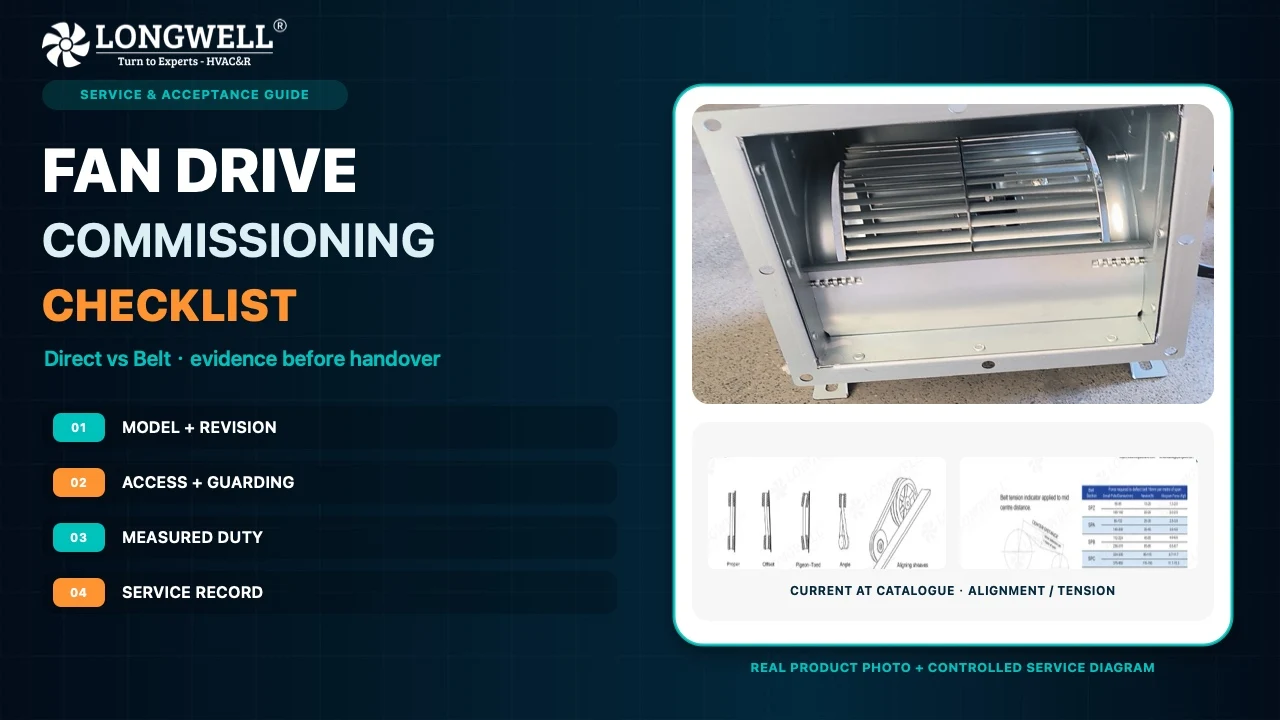
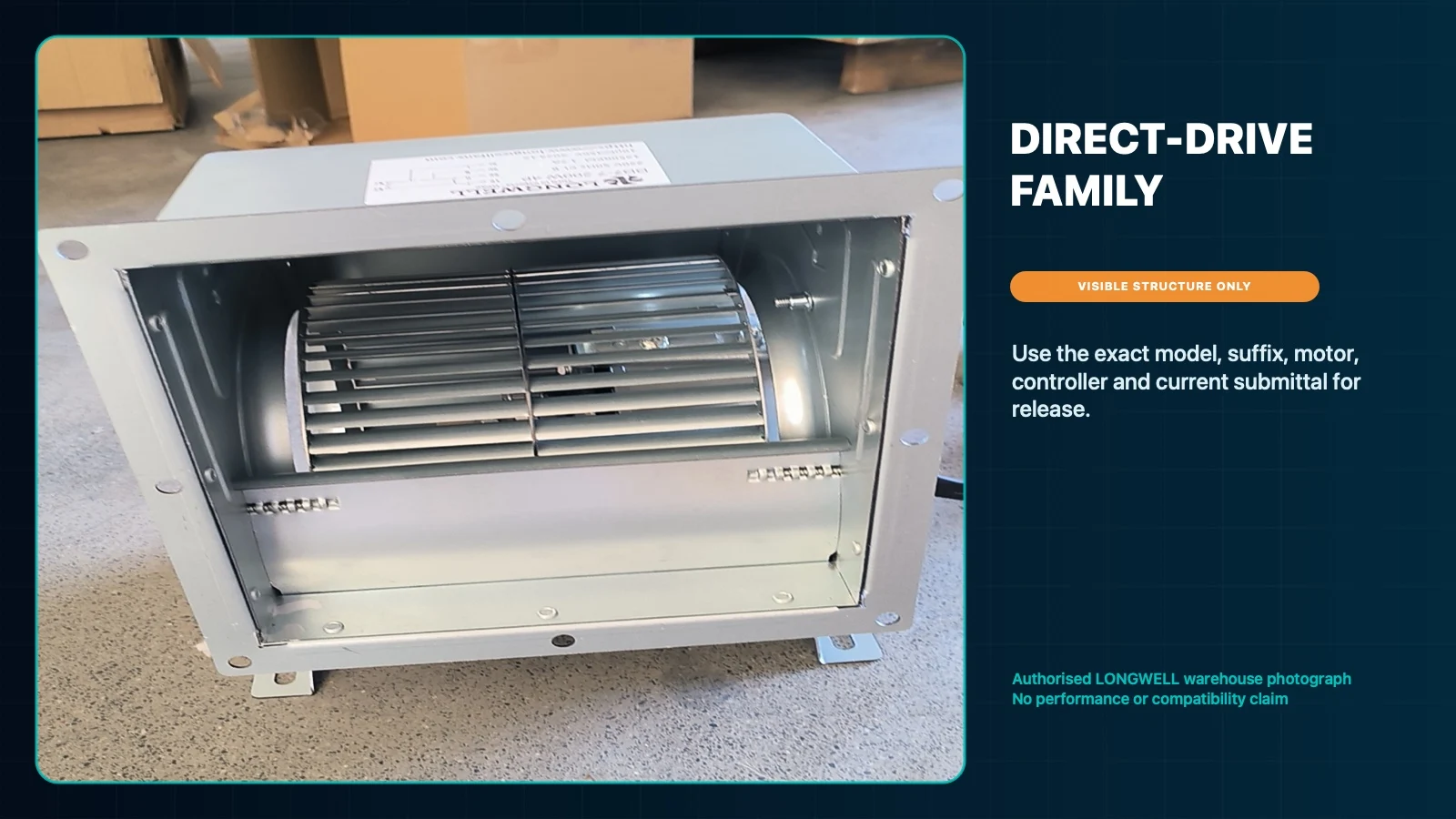
The current direct-drive centrifugal fan family is a discovery route, not an approval for the photographed assembly or a substitute for its current submittal. Record which parts can be serviced separately and which require an assembly replacement; that distinction matters to the spare-parts plan.
For belt drive, release the transmission as a system
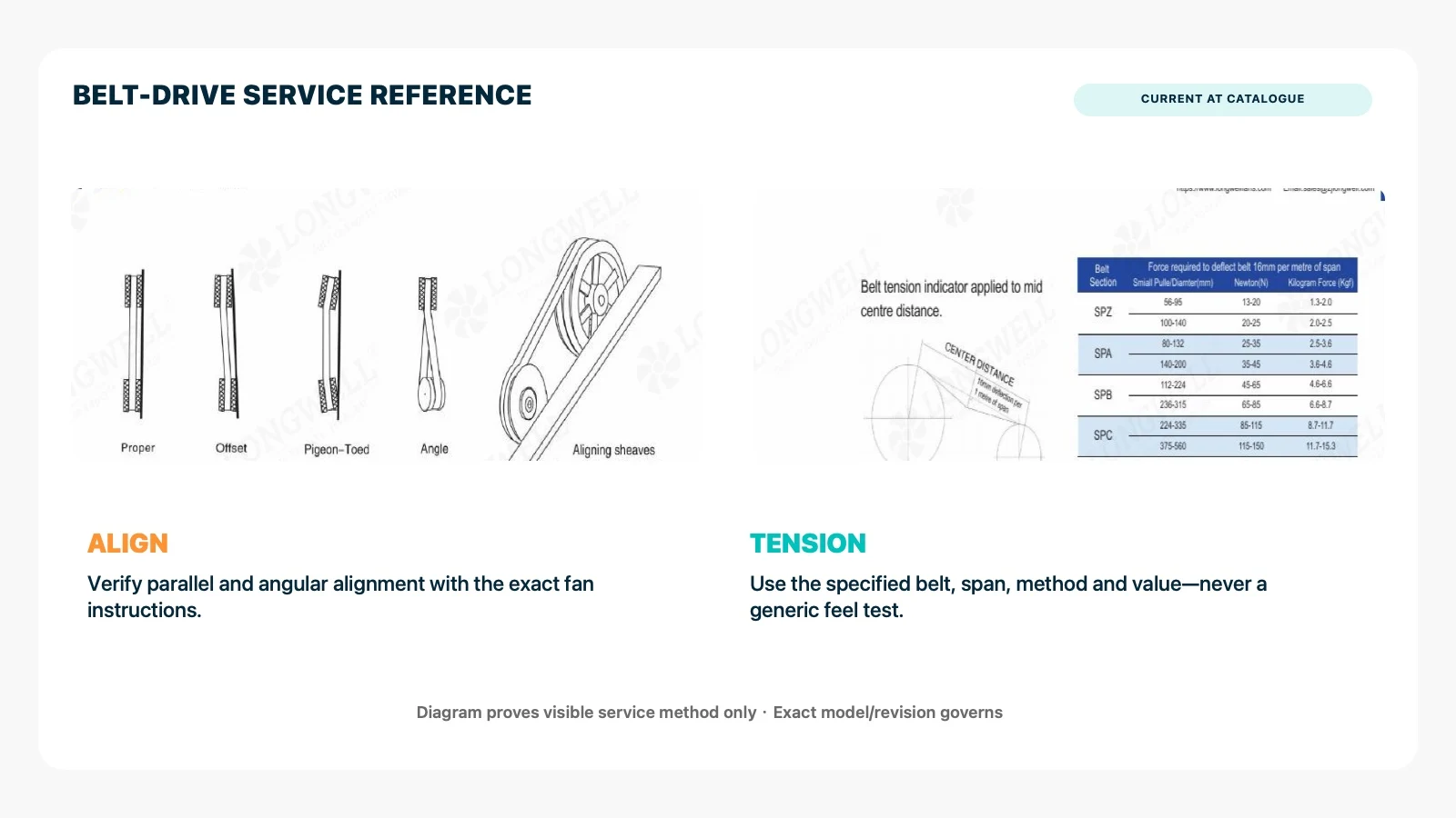
Begin with isolation and the fan maker’s instructions. Check the fan and motor shafts, sheave identity and condition, keys and bushings, parallel and angular alignment, belt section and matched set, center distance, guard fit, bearing mounting and lubrication provisions. Belts should be installed without levering or forcing them over the sheaves.
Tension is a measured setting, not a thumb-pressure opinion. Use the specified belt, span, method and installation value, then follow the manufacturer’s run-in and recheck instruction. Too little tension can permit slip and heat; too much can add bearing load. Changing a sheave changes fan speed and can change airflow, pressure, absorbed power, sound and mechanical loading, so it is an engineering change rather than a casual service adjustment.
The belt-driven centrifugal fan family helps locate relevant product documents. It does not establish the correct belt, tension, lubricant, interval or speed limit for a different model.
Close guards and mechanical checks before energising
With power safely isolated, remove foreign objects, turn the wheel by the approved method and check for rubbing, tight spots or unexpected movement. Confirm fasteners, supports, access doors and flexible connections. Belt drives need a complete, secure guard over the transmission; direct-drive arrangements may still have exposed rotating parts or access hazards. Apply the site’s electrical isolation and machine-guarding procedure rather than treating this article as a safety standard.
Do not run a fan with a temporary obstruction, open access panel or defeated interlock merely to “see whether it works.” Resolve the mechanical condition first.
Commission against one declared measurement boundary
Jog only as permitted to confirm rotation, then run the planned operating points. At each point, record command or frequency, fan speed where available, airflow, pressure at the declared taps, air density or correction basis, voltage, current, complete package input power, vibration and sound observations. Note damper, filter and system state so another technician can reproduce the test.
Compare results with the exact accepted curve and motor limits, not a neighbouring model or an uncorrected catalogue condition. A lower input reading is not a pass if the delivered duty also fell. Likewise, a correct airflow reading does not excuse excessive current, unstable control, rubbing, belt wander, abnormal temperature or an unsafe guard. Investigate the system effect, instrumentation, speed, rotation and assembly before assigning blame to the drive type.
Turn handover into a service record
The acceptance pack should include the installed fan, wheel, motor and controller identities; document revisions; wiring and control map; final settings; curve used; measurement locations; instruments; test conditions; readings; photos of guards and service access; and every approved deviation. For belt drive, add sheave and belt identities, alignment result, tension method and value, bearing/lubricant instruction, run-in recheck and spare matched-set details. For direct drive, add controller parameters, command limits, fault mapping and the replaceable-unit boundary.
Assign owners and triggers rather than inventing one universal interval. The equipment and component instructions, operating hours, contamination, starts, temperature and observed condition should drive inspections. A trend in vibration, current, sound or tension is more useful than an undocumented “checked” box.
Use clear stop conditions in the RFQ
Stop acceptance when the exact model or revision is unresolved, the duty boundary is missing, rotation or maximum speed is uncertain, the motor/control map cannot be verified, a guard or service clearance is incomplete, a belt specification or tension method is absent, or measured duty conflicts with electrical or mechanical limits. These are information gaps to close, not reasons to choose a winner by label.
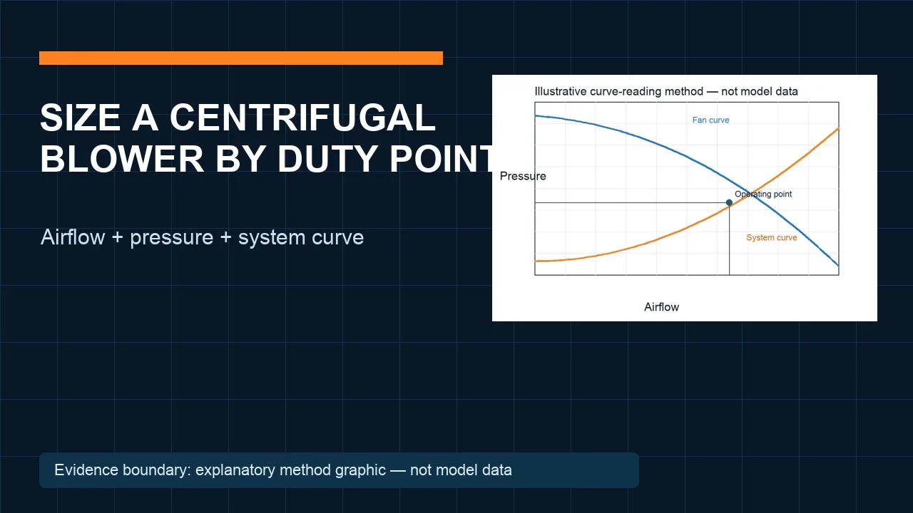
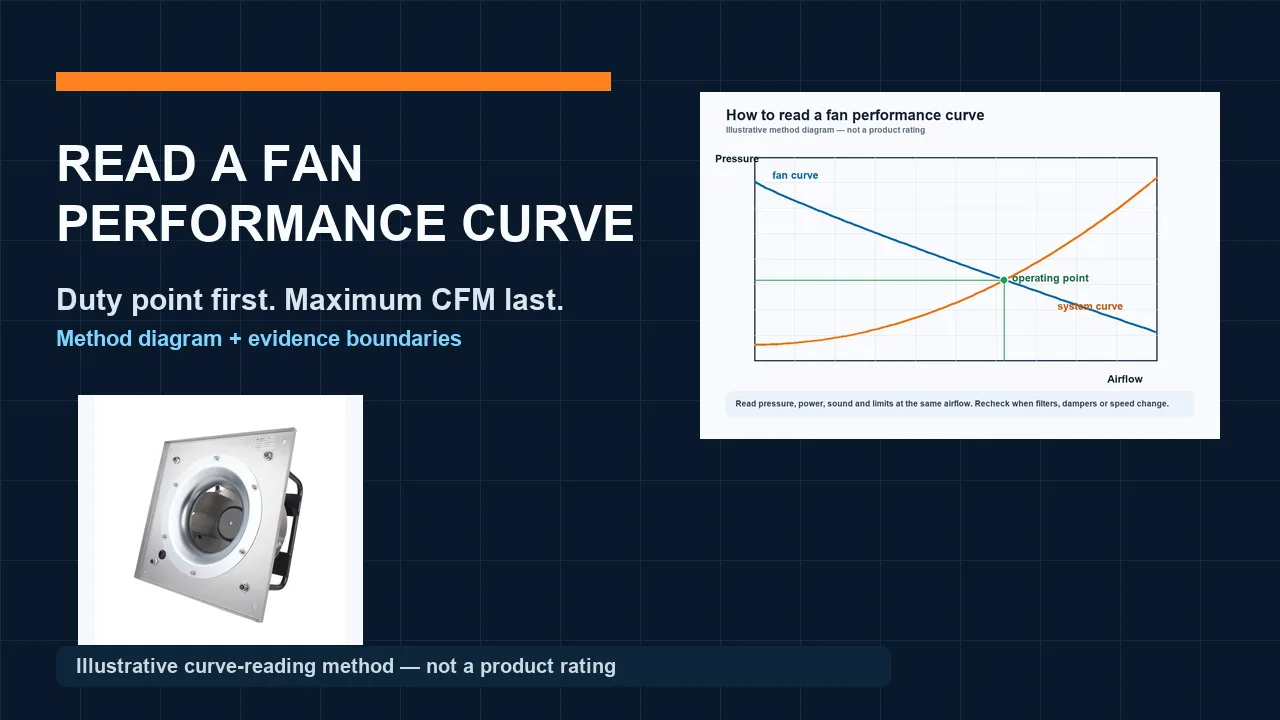
Send the supplier the duty and air condition, system sketch, inlet and outlet constraints, power and control details, orientation, access limits, environment, service capability and required acceptance records. Our centrifugal fan curve guide can help organise airflow, pressure and power evidence on one declared boundary. Final release still depends on a controlled model-specific selection, documents and commissioning plan.