A fan that moves plenty of air on an open bench can deliver much less after a filter, coil and ductwork are connected. The installed system adds resistance, so the fan must create pressure while moving air. Static pressure is the pressure available to overcome that resistance, measured relative to a stated reference. It is not another name for airflow, and one number cannot replace a complete duty point.
Static pressure and airflow answer different questions
Airflow tells you how much air passes through a section in a given time. Static pressure describes pressure potential at a location. In a duct, imagine the static component pressing against the wall in every direction. By contrast, the moving airstream also carries a velocity-related component.
This distinction matters during selection. A free-air airflow value is measured with little external resistance. It does not show how much flow remains after real equipment is connected. The useful question is therefore not “What is the maximum airflow?” but “What airflow does this fan provide at the required pressure?” Our practical guide to reading centrifugal fan curves explains how to find that paired operating point.
Static, velocity and total pressure are related
For low-speed air systems, total pressure is commonly treated as static pressure plus velocity pressure. Velocity pressure depends on air density and the square of air velocity. Changing duct area can therefore change velocity and the measured pressure components even while the same volume continues through the system.
The terminology still needs a defined boundary. Fan static pressure, fan total pressure and external static pressure across a finished air-handling unit are not automatically the same quantity. A buyer should confirm what the curve reports and make the project requirement use a compatible definition.
Tap direction and reference determine the reading
A wall static tap is flush with the duct wall, with its opening perpendicular to the main flow. A probe facing upstream senses the impact of the moving air as well and serves a different measurement purpose. That small difference in orientation can change the result enough to mislead a comparison.
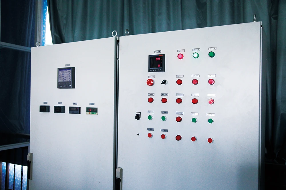
A manometer reports a pressure difference, not an isolated absolute value. The instrument needs a known reference and a recorded sign convention. A suction-side point may be below room pressure while a discharge-side point is above it. Record the tap locations, reference condition, instrument setup and whether each result is static or total pressure.
The fan curve and system curve meet at one operating point
Filters, coils, grilles, elbows, dampers, silencers and duct runs all add resistance. Together they form the system curve. The fan has its own pressure-versus-airflow curve at a stated speed and air condition. Where the two curves intersect is the expected operating point.
This is why maximum airflow and maximum pressure should never be combined as though they occur together. They are different ends of a curve. Start with the required airflow and the resistance of the complete path, then verify the matching point on controlled fan data. Buyers comparing suitable architectures can review the centrifugal fan series without treating a category page as model-specific performance proof.
Clean and dirty resistance belong in the same review
A clean filter is only the starting condition. As it loads with dust, resistance rises and the system curve shifts. At fixed speed, the intersection with the fan curve usually moves toward lower airflow. A control strategy may compensate, but only within the fan, motor and controller limits.
For procurement, request both clean and design-dirty resistance where filtration is involved. Also identify any coil, heat exchanger, grille or damper condition used in the calculation. This turns static pressure from a catalogue label into a boundary condition that can be checked at commissioning and during maintenance.
What a real test-room image proves—and what it does not
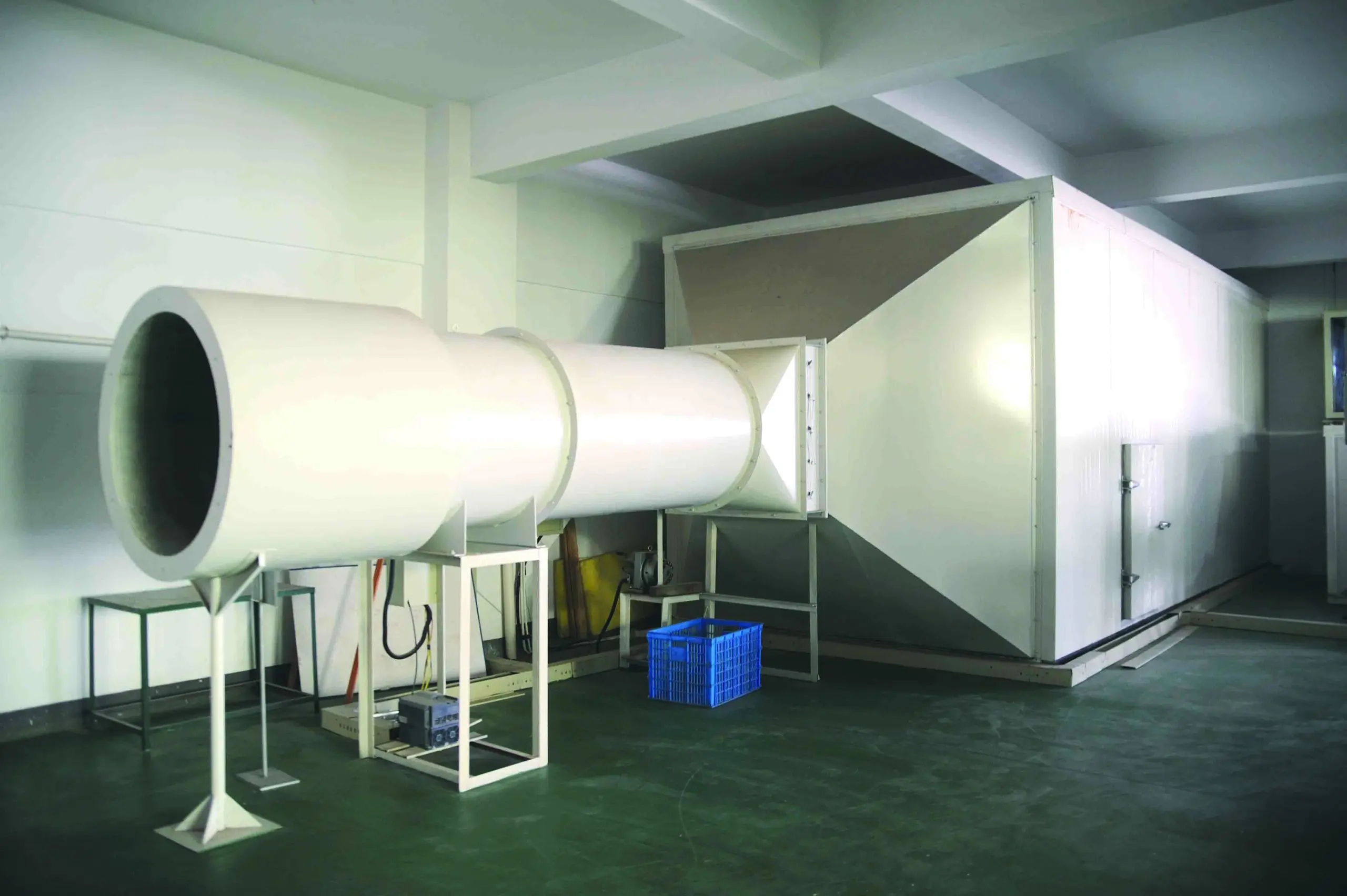
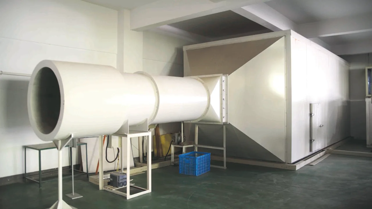
The image above shows a real Longwell airflow-test environment and visible duct/test hardware. It helps explain why measurement planes, flow paths and instrumentation matter. It does not, by itself, prove a particular pressure, airflow, efficiency, certification or model result. Those claims require the controlled record for the exact tested configuration and revision.
That evidence boundary is useful when reviewing supplier material. A laboratory photograph can establish physical context. It cannot safely transfer one fan’s readings to another size, impeller, motor, voltage, speed or housing. Ask for a curve or test record that preserves the product identity and the actual test conditions.
A better RFQ starts with a complete duty point
- Required airflow and required pressure at the same operating point
- Pressure definition and measurement boundary
- Air temperature, altitude or density if different from standard conditions
- Clean and design-dirty resistance, plus major system components
- Fan identity, size, speed, motor supply and control method
- Mechanical interface, orientation, sound target and acceptance method
If the system is still being defined, send a simple airflow-path sketch with the duty data. Longwell can then discuss the product boundary and the evidence needed for a defensible selection. For broader application planning, see our air-movement solutions overview before narrowing the request to an exact fan configuration.
The short version is simple: airflow states how much air must move; static pressure describes the resistance the fan must overcome. Keep the two values paired, define the measurement boundary, and verify the result against controlled data for the exact configuration.