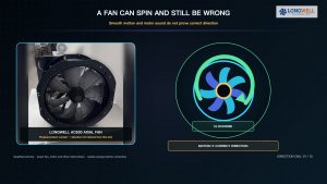
A grow room and a greenhouse can both have a running fan while air near the crop remains warm or humid. The right question is not simply how many cubic metres per hour a fan moves in free air. It is whether the complete inlet, crop zone and outlet path delivers the conditions the crop needs when screens, filters, shutters or pads are in their operating state.
This guide separates two different decisions. A compact, enclosed grow room usually needs a planned makeup-air and exhaust path through a filter and duct. A greenhouse also needs outdoor-air exchange, but its circulation fans perform a separate job inside the house. Start by recording the crop, layout and control targets; choose the fan at the installed duty only after the air path is known.
Begin at the crop, not the catalogue airflow number
Record the operating modes that matter: lights on and off, irrigation or misting, seasonal outdoor conditions, and any process that adds heat or moisture. Define the acceptable temperature, humidity and carbon-dioxide range for the actual crop and growth stage with the grower or agronomist. The same room may need different ventilation and circulation responses at different times. A single thermostat reading cannot tell you whether air reaches the most crowded leaves.
Locate representative sensors within or near the crop zone, away from a direct inlet jet, hot fixture or wet surface. Compare readings in several locations and modes before treating one reading as representative. The aim is to expose the hot, damp or stagnant pockets that a room-average sensor can miss.
For an enclosed grow room, trace the loaded exhaust path
Makeup air must enter through a deliberate opening, pass the plants and leave through the chosen filter, duct and exhaust fan. A filter can be a major resistance, and its pressure drop changes as it loads. A duct bend, silencer and outlet grille add further loss. List the components and obtain their actual clean and loaded pressure data; do not assign one generic pressure figure to every filter or installation.
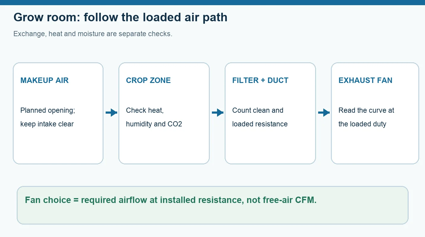
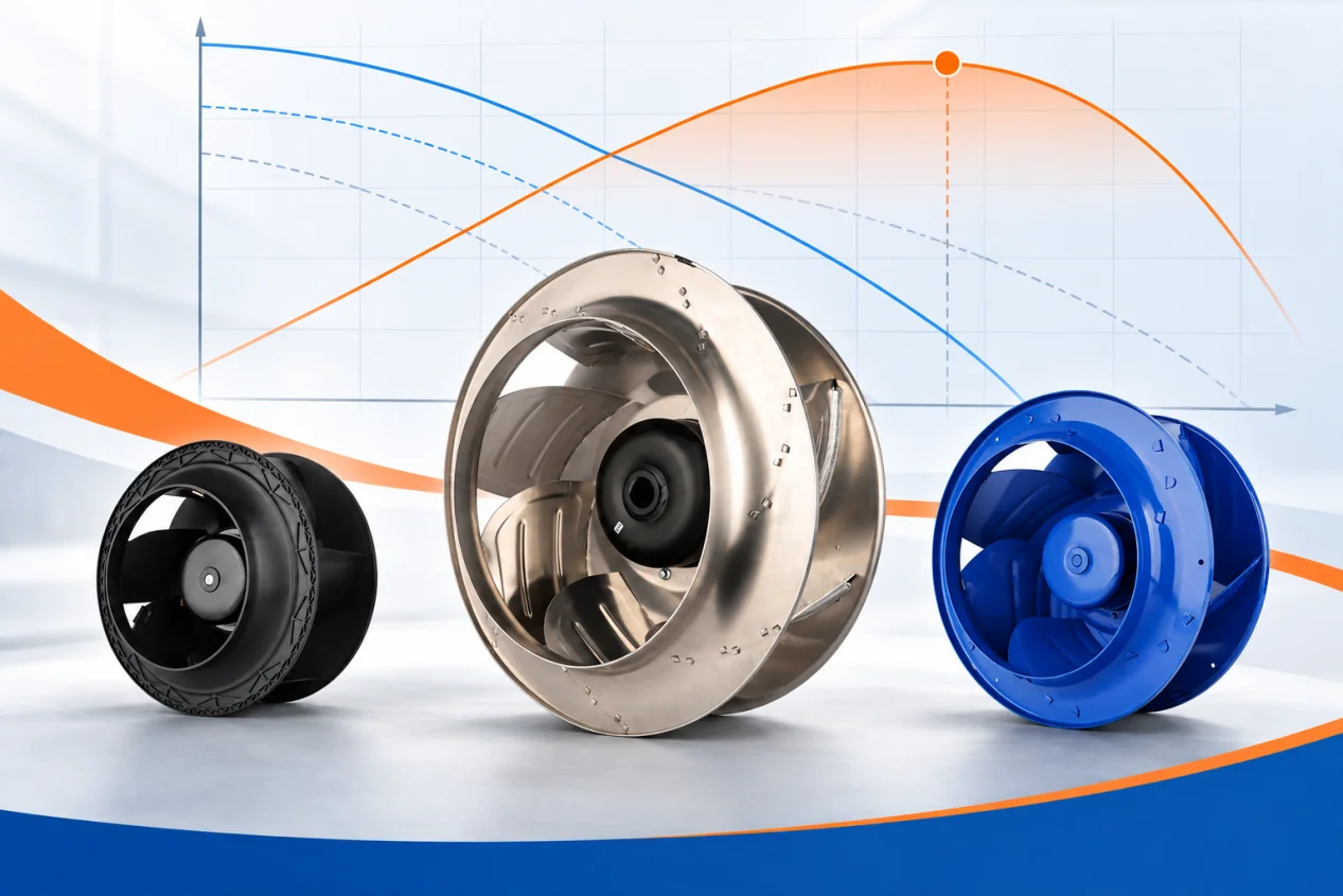
Choose the required exchange flow from the project’s heat, moisture, carbon-dioxide and odour-control requirements. Then compare that flow with the fan curve at the combined operating resistance. The free-air rating is one endpoint of the curve, not the flow delivered through the assembled system. If the room must remain under a specified pressure relationship, verify it with the actual inlet and outlet configuration; stronger suction alone is not a substitute for a designed air path.
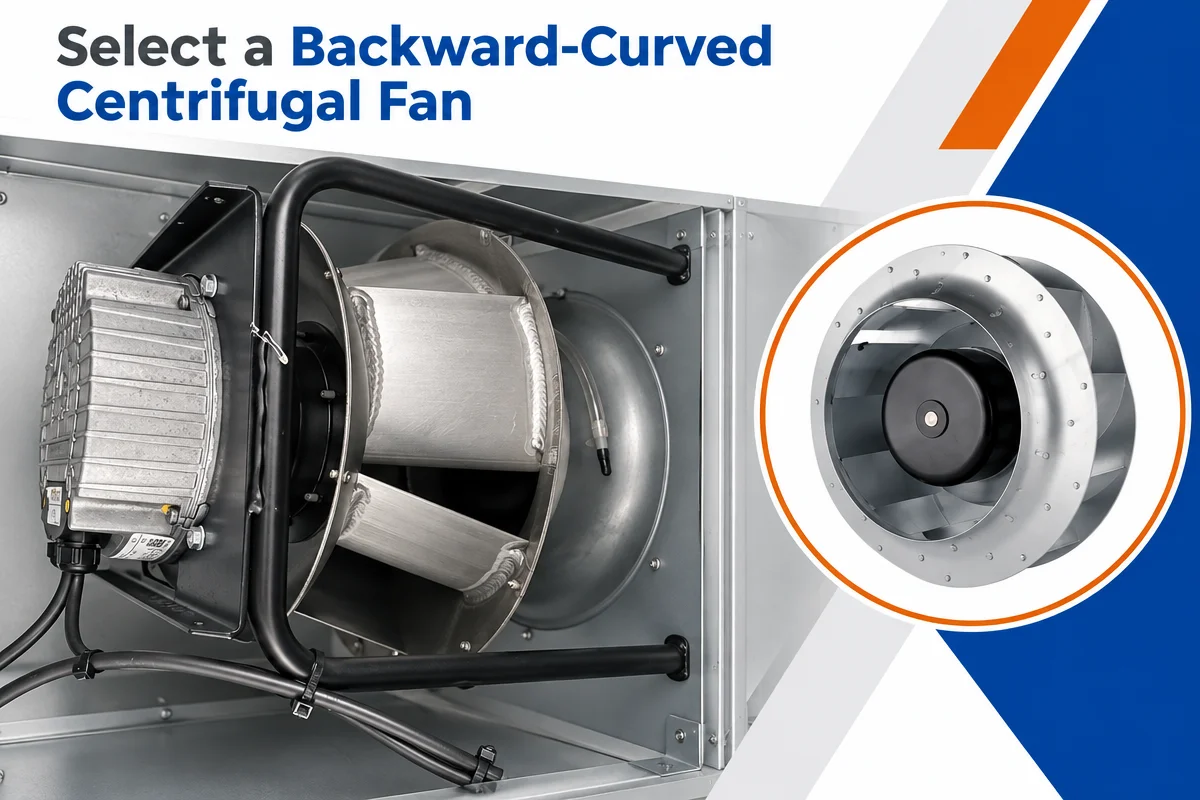
A LONGWELL inline duct fan family can be a useful product starting point for a ducted layout. A family page identifies available architecture; it does not establish a filter-compatible duty or an exact grow-room fit. Request the current curve, control interface and electrical data for the exact candidate model before selection.
For a greenhouse, keep exchange and circulation separate
Outdoor-air exchange removes accumulated heat and moisture when outside conditions permit. The inlet, crop aisle or canopy path and exhaust location determine whether replacement air actually reaches the plants. Circulation fans move air around the house to reduce local stagnation and stratification; they do not, by themselves, replace stale indoor air with outdoor air. Conversely, a large exhaust total does not guarantee an even canopy environment if incoming air short-circuits above the crop.
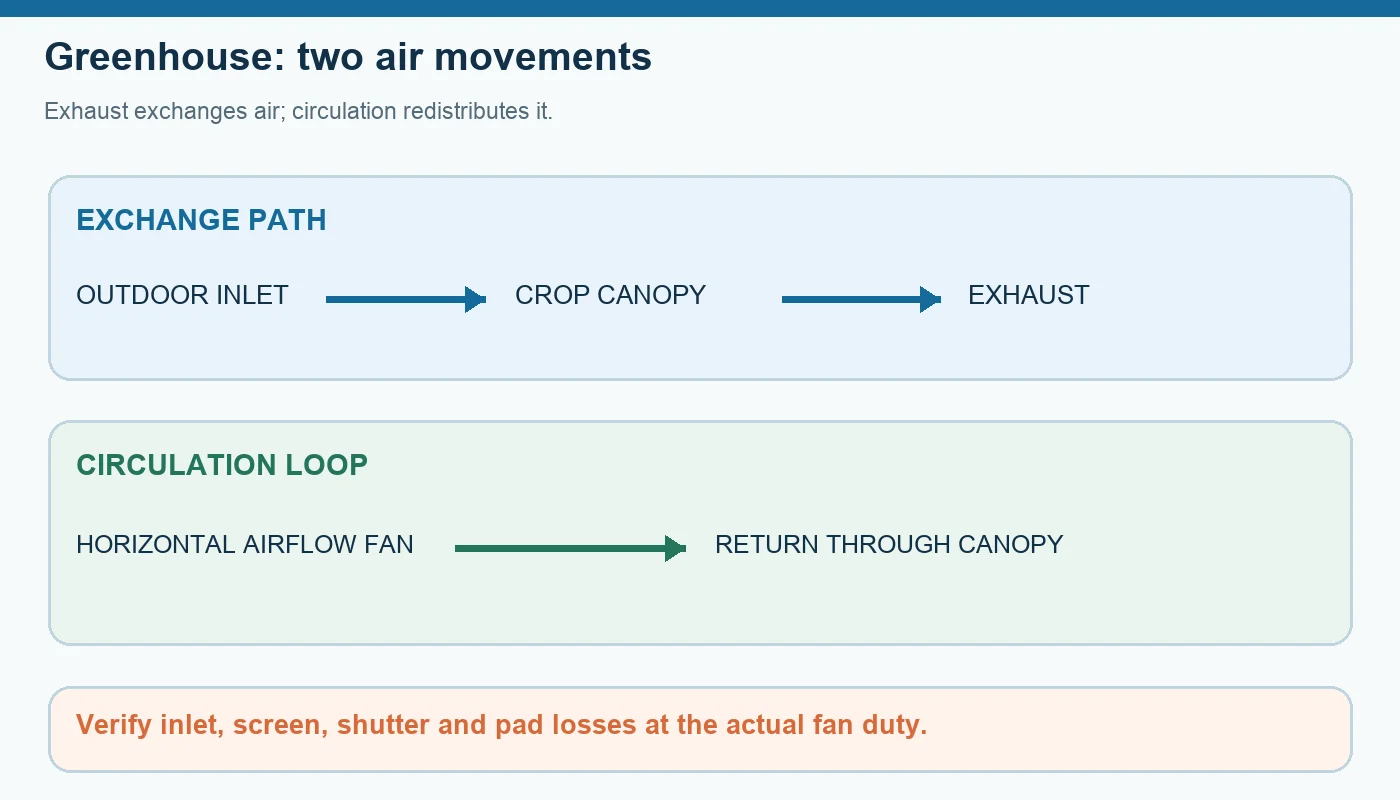
Map both paths on a plan and sectional view. Mark benches, tall crop blocks, shade curtains, open vents, insect screens, shutters and any evaporative pad. Check whether changes in crop height or blocked aisles alter the route. University of Maryland Extension also discusses how greenhouse air circulation can help keep foliage drier; the crop and disease context still determines the control target. This is a reason to inspect the canopy, not a universal fan-spacing prescription.
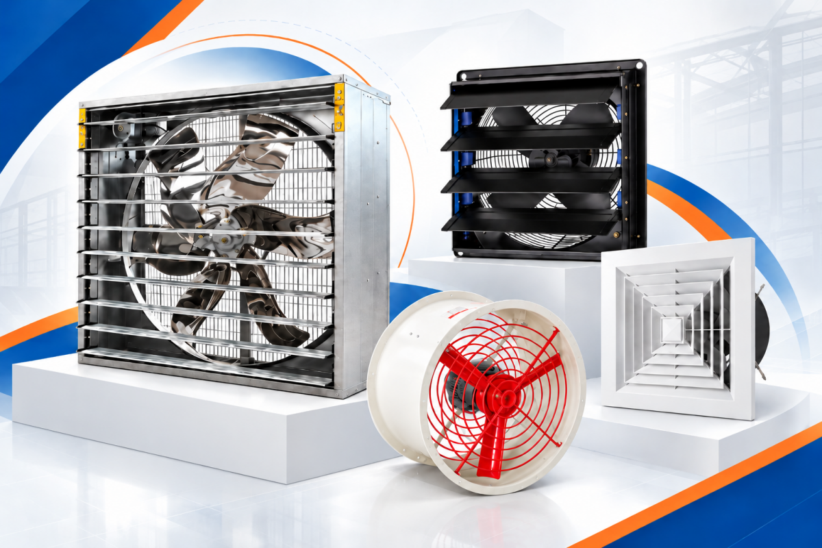
The LONGWELL industrial axial fan family shows a possible high-volume exhaust architecture, while the company’s greenhouse overview introduces the application. Neither page proves that a particular model will deliver the required flow through this project’s screen, shutter or pad. The recorded AC800 video shows visible axial-fan construction only; it is not an installed greenhouse test or an exact-model recommendation.
Select against resistance at each operating state
For each proposed fan, collect the exact model and revision, performance curve, voltage and control method. On the system side, document the inlet and outlet geometry, duct or screen losses and the service condition that sets the highest expected resistance. Plot the required flow and pressure together. A fan can have an attractive maximum-flow value and still fall short after the installed restrictions are included.
Keep clean and loaded states distinct. In a grow room, a loaded carbon filter may change the duty; in a greenhouse, a dirty screen, closed shutter or wetted pad may change it. Do not combine unrelated losses into a made-up fixed allowance. For a step-by-step discussion of the greenhouse side, see the greenhouse fan selection guide. Confirm that the data behind any candidate curve matches the exact motor and wheel configuration being quoted.
Commission the air path, then tune controls
After installation, verify rotation, fan staging and the intended inlet or shutter response. Measure the actual system pressure and airflow where practical, and compare those observations with the design duty. Walk the crop zone in representative day and night modes; log temperature and humidity at more than one location, then look for bypass routes and still pockets. Check how the system behaves when a filter becomes loaded or a stage is unavailable.
The control sequence should respond to real conditions rather than run every fan at one setting. Document which signal starts exhaust, which starts circulation and which equipment is interlocked with pads, vents or filters. Include a safe response to sensor, fan and power faults. These checks reveal whether the installed path performs as intended; they do not turn a general article into a crop-specific control schedule.
What to send for a model-specific review
Provide the crop and growth stage, a plan and section of the structure, day and night environmental targets, local outdoor design conditions, internal heat and moisture sources, inlet and exhaust positions, filter or screen details, clean and loaded resistance data, power supply, control modes and noise constraints. Include the measurement plan for commissioning. With those inputs, an engineer can compare candidate fan curves at the actual duties and identify missing evidence before a model is selected.
For a project-specific fan review, email LONGWELL sales with the layout and duty data.
Choose the right duct fan
Longwell manufactures 254 duct fans in-house. Send airflow, static pressure and voltage — an engineer replies with a matching model, performance curve and price within one working day.