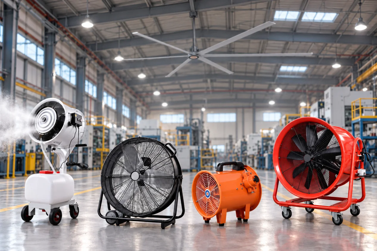
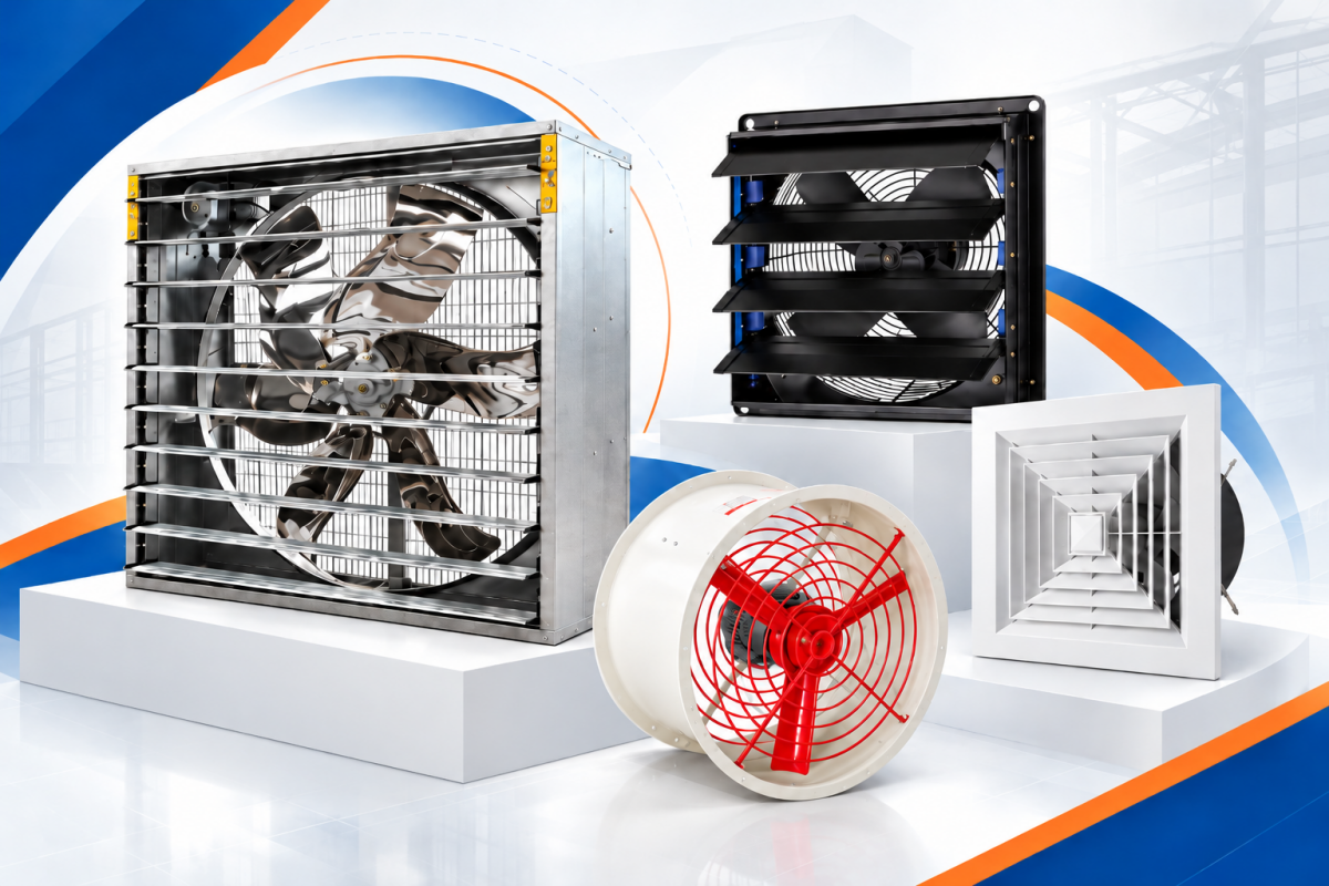
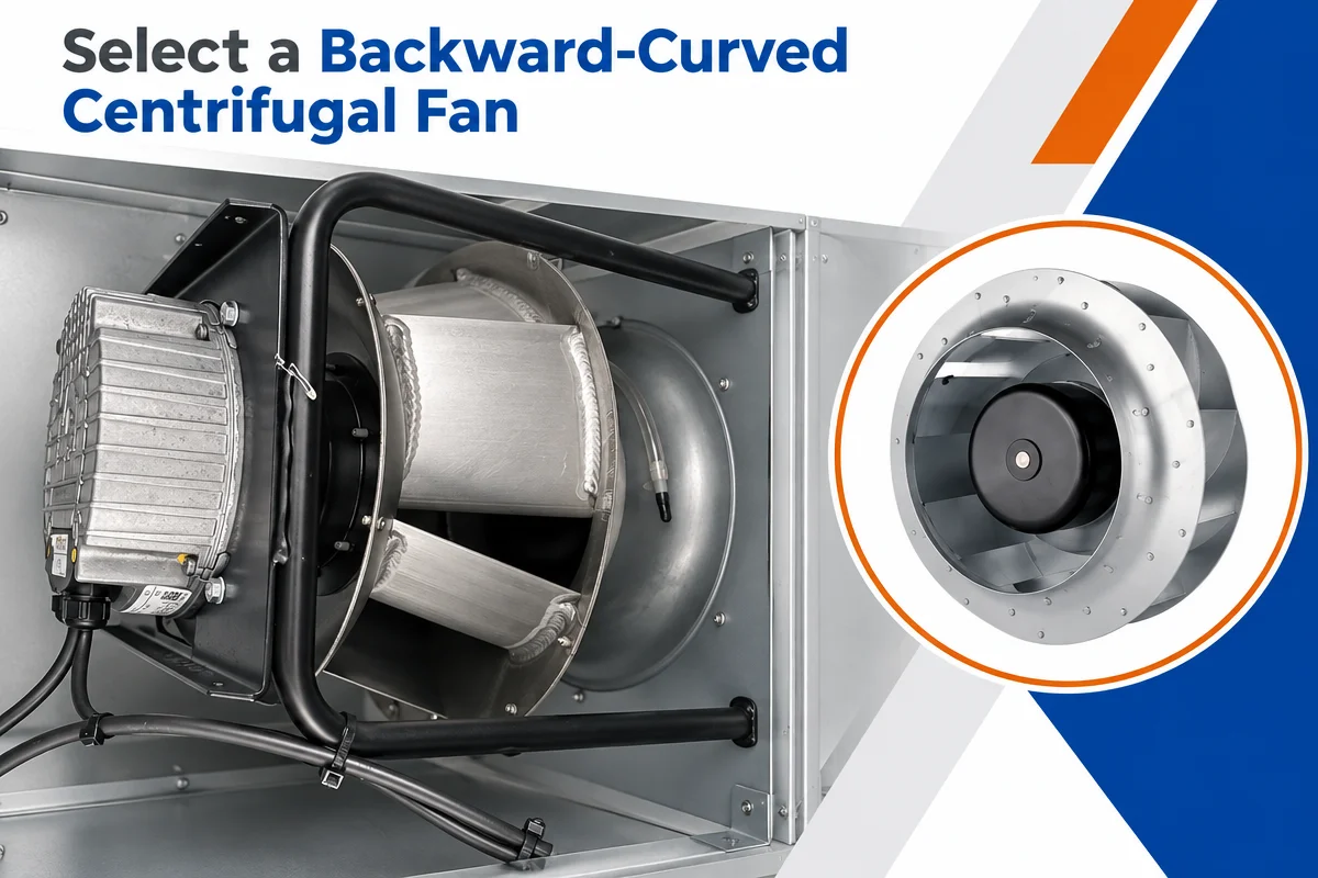
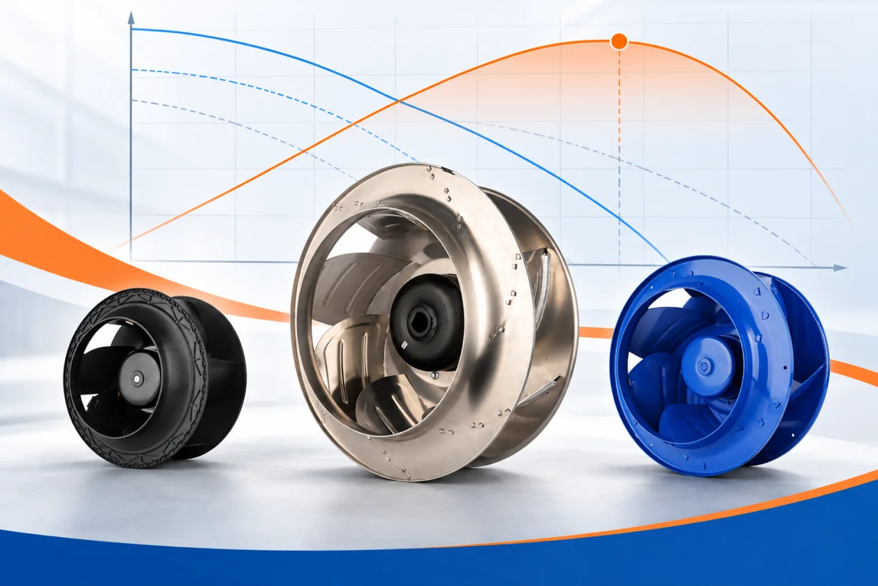
A speed-control label cannot tell you which fan system will use less electricity. The decision depends on the airflow and pressure required at each operating state, how many hours that state occurs, and the electrical input of the complete fan and control assembly at the resulting duty point. Fixed speed, two speed and variable speed are three ways to meet those states; none is a guaranteed energy or cost ranking.
Start with the duty states
Write down the required flow, pressure basis, air density, filter condition and operating hours before comparing controls. A process with one genuinely constant duty may have no useful lower-speed period. A process with two validated operating states can be evaluated for two-speed control. A continuously changing demand may justify a variable range, but only if the fan can safely serve every required point in that range. A timetable alone is not proof of two distinct airflow requirements; measure or specify the actual demand.
Use the same service boundary for every option. If one proposal includes a damper, bypass, standby draw or different filtration condition, account for it explicitly. Do not compare a bare motor rating against another proposal’s complete electrical input.
What each control route actually provides
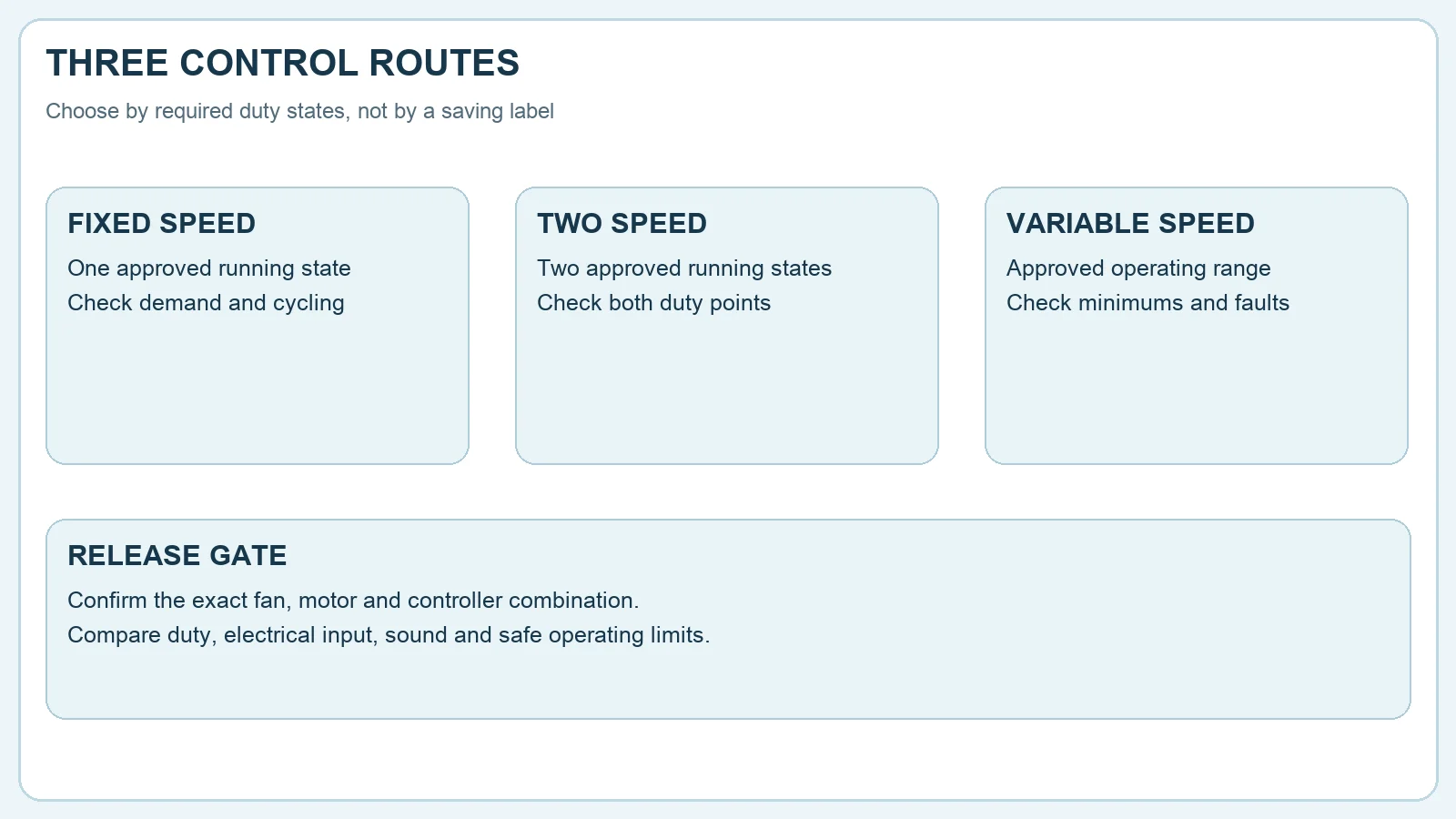
A fixed-speed assembly has one approved running speed. Output may still be changed by cycling, a damper or staging separate fans, each with its own system and safety consequences. A two-speed assembly has two approved running states; their available duty points and motor arrangement must be confirmed for the exact combination. A variable-speed assembly accepts commands over an approved range, subject to motor, drive, impeller, vibration and process limits.
Variable speed is an operating concept, not a synonym for a specific motor technology. An AC motor with a compatible VFD and an EC fan with integrated electronics can both provide speed control, but their wiring, control inputs and protection requirements differ. The LONGWELL EC backward-curved fan family is a family-level starting point for identifying candidates; its listing does not establish that any particular model meets this article’s example duty.
Use fan laws as a screening tool
For comparable geometry and air density, fan-law relationships can estimate how flow, pressure and fan shaft power change with rotational speed under appropriate system conditions. They are useful for screening a candidate, not for asserting that a facility will save a fixed percentage. The system curve and fan curve set the actual operating point. Static pressure that does not scale with flow, changing filters, control losses, motor efficiency and operating limits can move the real electrical result away from a simple cube-law estimate.
The US Department of Energy’s fan system sourcebook discusses both speed reduction and multiple-speed motors, while noting the need to consider motor behavior and the full system. For another explanation of part-load effects, see our part-load fan energy guide. Treat illustrative percentages there as scenario calculations unless the exact candidate and system have been measured.
Calculate annual energy by load bin
For each valid operating state, obtain the complete electrical input at the required flow and pressure. Multiply that input by documented annual hours, then add the bins. Include controller consumption, standby, bypass and cycling where applicable. Use the same air density, filter assumptions and process safety minimums across candidates. If an input value comes from a catalogue point, verify that the exact model, revision, voltage, speed and test arrangement match the proposed installation.
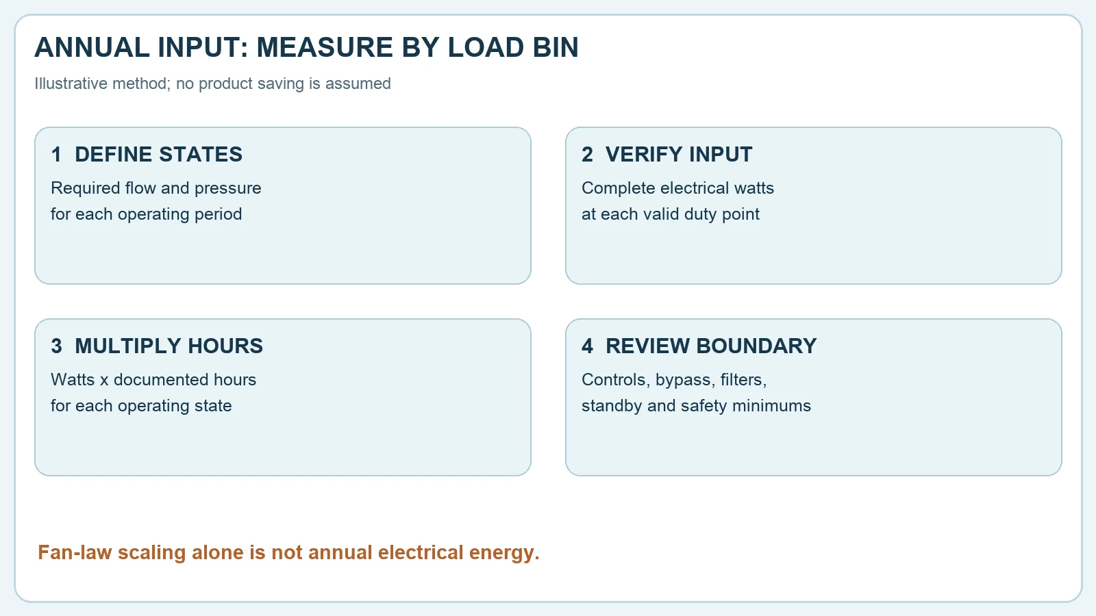
For example, a site may have a normal state, a reduced-demand state and an off state. That is a method for organizing the comparison, not a claim that a two-speed or variable-speed solution will always win. If the reduced state cannot meet the required ventilation or cooling duty, it is not a valid energy-saving state. If operating hours are unknown, log them before predicting payback.
Check the entire fan and control package
Confirm the proposed fan curve, motor and drive compatibility, supply, starting behavior, speed limits, stable range, vibration, sound and protection functions. For a VFD proposal, review the exact motor insulation and drive installation requirements, cable length, grounding, electromagnetic compatibility and bearing considerations with the relevant manufacturers. For any control type, define loss-of-signal behavior, restart after power loss, alarms and the minimum process airflow.
Changes in speed can alter the fan’s operating point and sound character. Check the installed inlet and discharge geometry, not only a free-air catalogue maximum. Our VFD compatibility guide lists questions to settle before applying a drive to an existing fan; it is a screening aid, not approval for a particular motor.
A practical selection rule
Keep fixed speed in the comparison when one duty dominates and measured electrical input is competitive. Evaluate two speed when two distinct, safe duty states cover a meaningful share of the schedule and the exact assembly has approved performance at both states. Evaluate variable speed when demand spans a useful range and the control package can be commissioned across it. Compare total annual input and lifecycle obligations only after each option meets the same service and safety requirements.
Release the choice with exact fan, motor and controller identifiers; curves or measured duty points; the annual load-bin schedule; electrical boundaries; minimum-flow and speed limits; and a commissioning plan. If these inputs are missing, the honest result is a shortlist for testing, not a claimed savings figure.
Watch the control comparison
The video below walks through the fixed, two-speed and variable-speed decision. Use it alongside the duty-point and load-bin checks above rather than as a substitute for a model-specific submittal.
For an application-specific fan and control review, email LONGWELL sales with your duty states and operating hours.