An evaporator fan can be spinning while useful airflow through the coil is already falling. Frost, a wet coil, a restrictive guard, a changed rotation, or a poor return path can move the installed operating point away from the clean-coil catalog condition. That is why cold-chain fan selection must cover the whole operating envelope, not just a diameter or free-air number.
This guide is for cold-room OEMs, refrigeration contractors, and facility teams choosing or replacing evaporator fans. It makes no universal claim for room capacity, energy savings, minimum temperature, defrost delay, service life, or payback. Those results depend on the exact fan, coil, room, controls, installation, and verified test conditions.
Define the Fan Duty Before Comparing Motors
Start with the evaporator as a system. The fan must move air through the coil, guard, housing, and nearby obstructions, distribute it across the product zone, and return air without a short circuit. Record the required airflow and pressure definition, coil data, room setpoint, product load, door traffic, altitude, mounting space, allowable sound, power supply, and control interface.
A motor nameplate or impeller diameter is only a partial replacement reference. Verify rotation, blowing or suction arrangement, blade and guard geometry, mounting pattern, depth, cable exit, clearances, and service access. Longwell’s EC axial fan range is a product-family starting point; it is not evidence that any catalog model will meet a particular evaporator duty.
Select at Clean, Wet, and Allowable-Frost Conditions
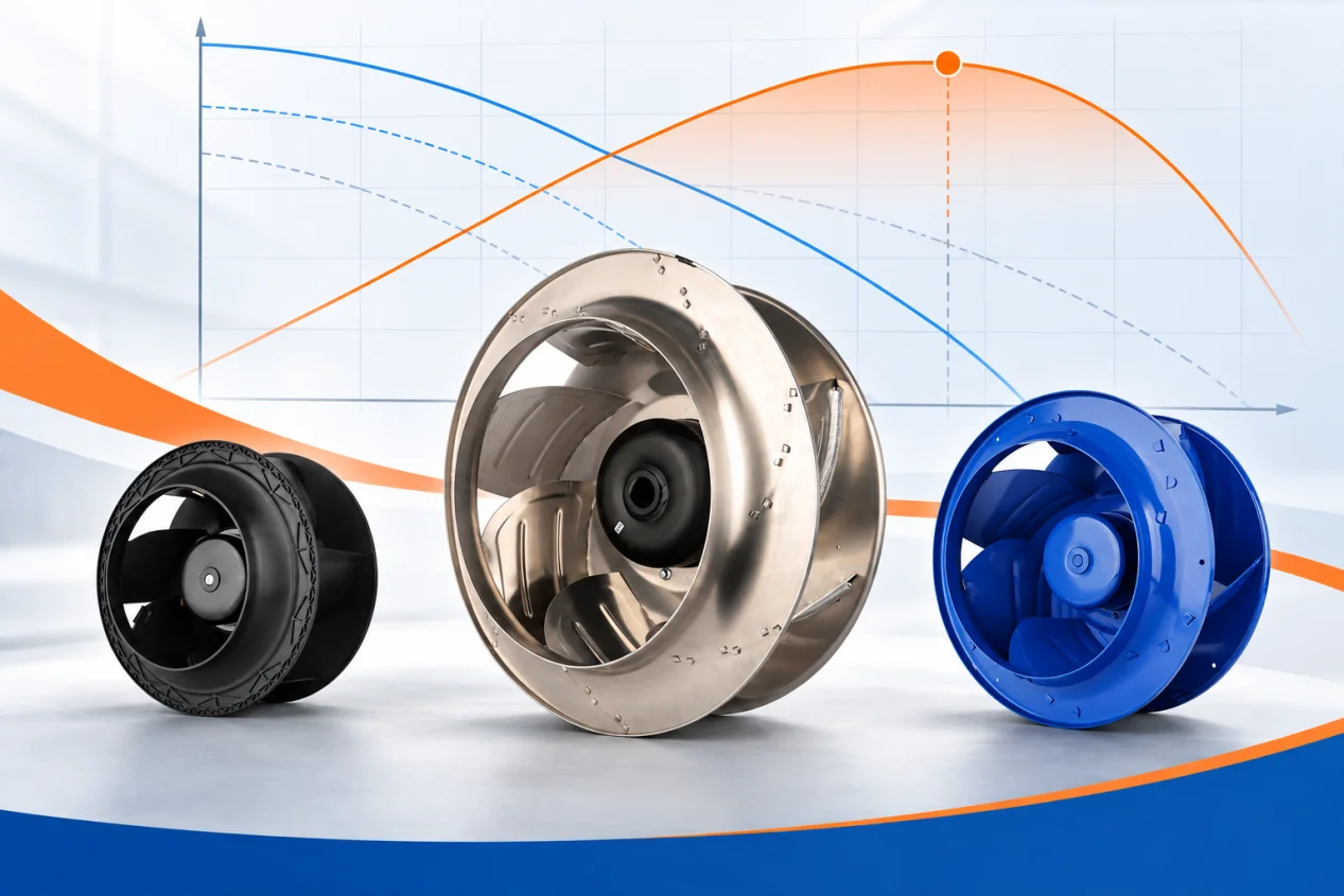
A fan operates where its performance curve intersects the installed system curve. Coil resistance changes as surfaces become wet and frost accumulates, while guards, housings, and poor inlet or outlet conditions can add system effects. Plot or otherwise verify the required operating points for the clean coil, the expected wet condition, and the maximum allowable frost state before defrost.
At each point, check delivered airflow, fan input, speed, current, motor limits, stability, and the farthest product zone. Do not use free-air airflow as installed airflow. Do not assume a higher-speed fan will correct a blocked coil or an air path that sends supply air directly back to the inlet.
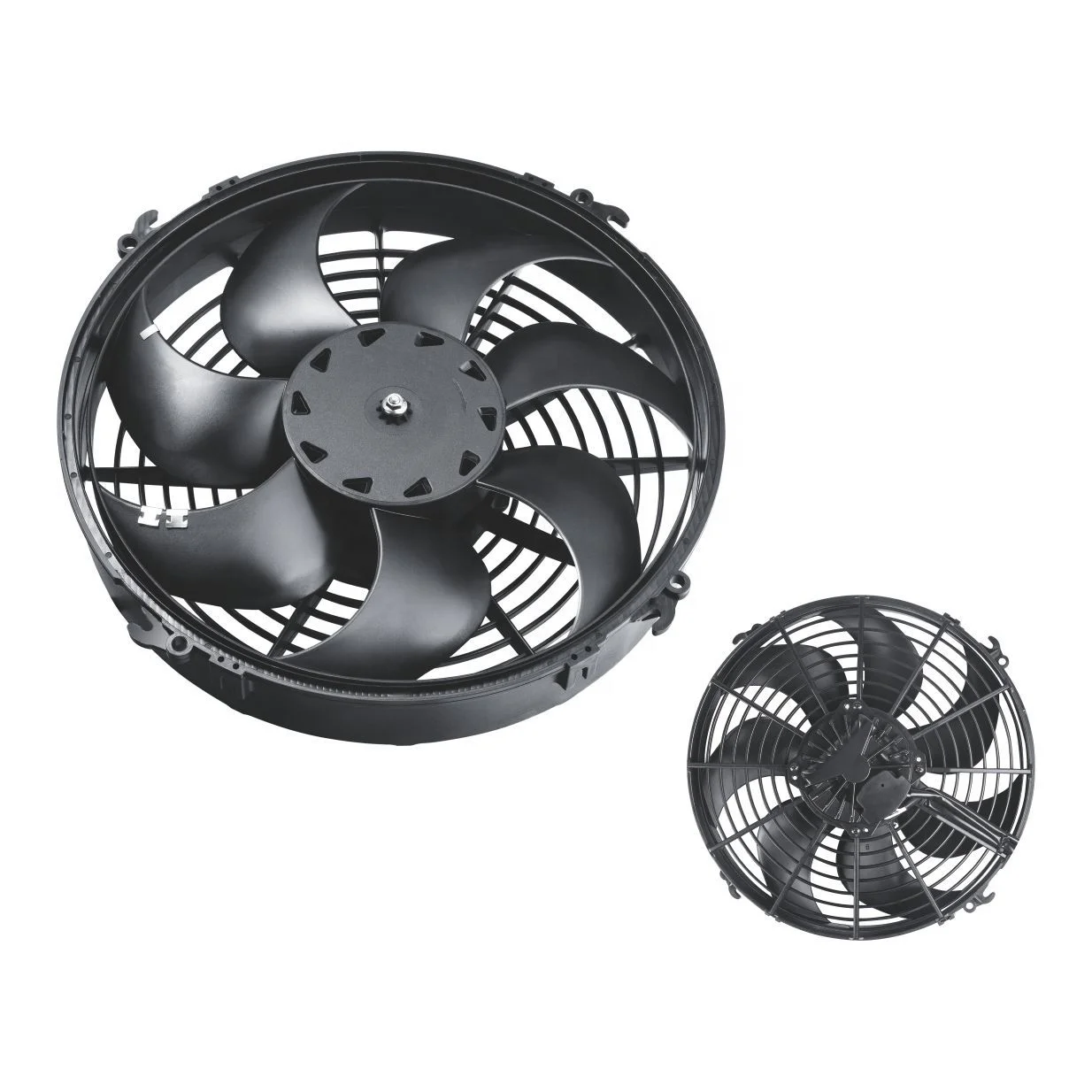
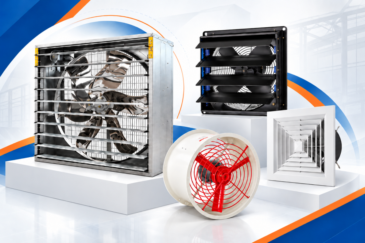
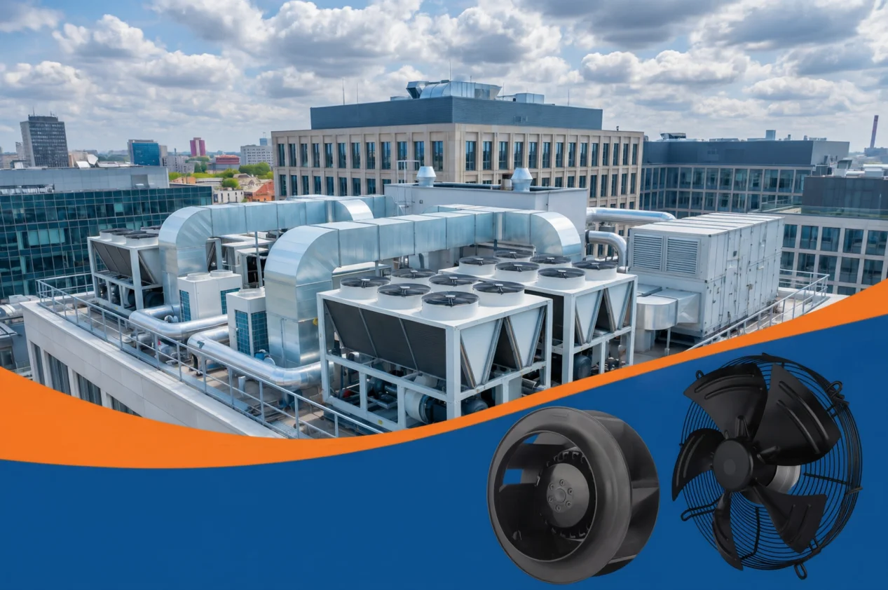
The product photograph shows two Longwell axial fan configurations from the current cold-chain materials library. It establishes product-family identity only; it does not prove a model, operating point, low-temperature rating, protection class, certification, or suitability for a specific room.
Qualify the Exact Motor for Cold, Moisture, and Cleaning
Cold changes lubricant behavior and material response, while defrost adds heat, water, and condensation. Confirm the exact model’s minimum and maximum ambient rating, enclosure protection, insulation system, bearings and lubricant, thermal protection, locked-rotor behavior, cable entry, connector orientation, and approved cleaning exposure. An IP code describes specific test conditions; it does not automatically prove resistance to every washdown method, chemical, drainage problem, or freeze-thaw cycle.
The current Longwell catalogs list several LWFC evaporator-blower and LWCC axial-fan families, with model-specific differences in voltage, airflow, pressure, protection, temperature, and control features. Use the dated datasheet and drawing for the selected model. The broader cold-chain solution portfolio can help identify families to review, but its application examples are not a substitute for exact-model documentation and project validation.
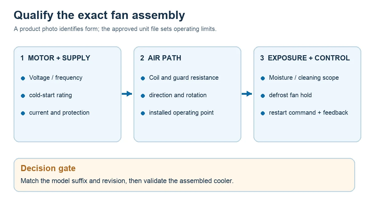
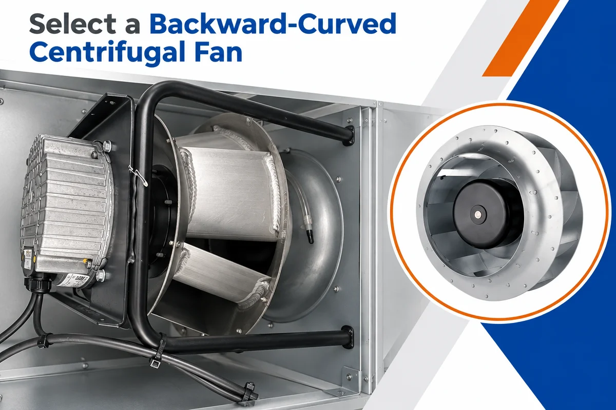
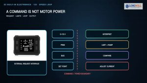
Use the diagram to turn the model review into three checks: the exact motor and supply, the installed coil and guard air path, and the moisture and defrost-control boundary. No single catalog image establishes all three. Ask for the current drawing, curve and controller sequence for the chosen suffix and revision.
Treat Defrost and Restart as a Control Sequence
Define what commands the fan during cooling, pump-down if used, defrost, drip time, fan hold, and restart. The correct sequence is evaporator- and controller-specific. A fixed delay copied from another unit can restart too early, distribute warm wet air, or restart too late and reduce temperature recovery.
Document the restart condition, not only the timer value. Verify controller output, fan enable, speed command, feedback, alarms, and fail-safe state. If variable-speed operation is proposed, confirm the minimum approved speed and motor cooling across the actual control range. Efficiency or energy-savings claims should come from measured input at matched airflow and pressure, plus documented hours in each operating mode.
Commission the Air Path, Not Just the Fan
Commission with the coil clean, at representative product load, through a normal door event, at the allowed frost condition, and through defrost and restart. Map temperature and airflow at supply, return, and remote product locations. Record speed, current, power, vibration, sound, command, feedback, coil condition, and test timing with identified instruments.
Separate symptoms before replacing hardware. For a fan that will not run, check the command, supply at the motor, wiring, protection state, and mechanical freedom. For weak airflow, check coil blockage, rotation, guard clearance, speed, current, and bypass. For uneven frost or room temperature, also inspect refrigerant feed, defrost coverage, door infiltration, supply throw, and the return path.
Send a Duty Package That Supports a Real Decision
A useful request for quotation includes room setpoint and extremes, product and door-load assumptions, coil model and pressure-drop data, required airflow and pressure points, allowable frost state, air direction, mounting drawing, clearances, voltage and frequency, control signals, environmental and cleaning requirements, defrost sequence, sound limits, and the acceptance test.
If an AC-to-EC change is being evaluated, use measured power at matched duty and documented operating hours. The AC-to-EC retrofit ROI guide provides a structure for the cost model; it cannot replace project measurements. The handover pack should retain the approved datasheet, curves, drawing, wiring, control sequence, commissioning record, and acceptance sign-off so the decision remains reproducible.