A layout conflict found in CAD, not on a line
An OEM developing an inverter air conditioner ordered prototype sets: a 615mm cross-flow impeller on a 24 VDC brushless motor. During 3D CAD integration they found a geometric conflict that turned into a fan rotation direction problem.
Their airflow path is specific. Air pulls down across a top-mounted heat exchanger inside 130mm of vertical clearance, then discharges through a 30mm exit port at the bottom left.
How geometry became rotation
That layout forces the motor onto the left side of the chassis rather than the right. Mirror the motor position and the impeller must turn the other way to keep the same intake-to-exhaust vector.
So the originally specified motor was suddenly wrong by one property: it turns counterclockwise, and the installation now demands clockwise.
The rest of the interface
- First, 1500 RPM rated load speed under PWM control, on the rectified 24 V rail.
- Next, a steel shaft exactly 25mm long and 8.0mm across, toleranced -0.01/0.
- Meanwhile no flat cross-cut on the shaft end, by explicit instruction.
- Finally, an immediate drawing update, because their integration schedule was live.
Why fan rotation direction is designed in
The tempting fix takes one wire swap. Reversing supply polarity spins a DC motor the other way, and everything about that shortcut is wrong for a product.
What reverse running actually costs
A motor is optimized around its intended fan rotation direction. Namely, the bearing preload, the magnetic geometry and the acoustic behavior all assume it.
Run it backwards and the bearings load on surfaces nobody chose for the job, the magnetics work off their design point, and the noise floor rises. None of it fails on day one, which is exactly what makes the shortcut dangerous: it ships.
The correct fix
Instead, we built a clockwise variant of the 92mm motor, designed for CW fan rotation direction at the 1500 RPM load point rather than persuaded into it.
Here the connector carries the same four wires, red 24 V, blue ground, yellow PWM in, white FG speed out, so the customer mainboard integration did not move at all. In other words, the change lives entirely inside the motor.
The impeller followed
Meanwhile the 615mm impeller kept its length and its 90.5mm diameter, with the hub and shaft interface updated to the new motor. A cross-flow impeller is handed too, since blade curvature works with the rotation, not regardless of it.
The shaft instruction worth noticing
Lastly, the customer explicitly banned a flat cross-cut on the shaft end. A flat is the easy way to lock a coupling, yet it concentrates stress and adds imbalance on a long slender rotor.
Their coupling grips a plain cylinder instead, which is why the -0.01/0 tolerance on the 8mm diameter is tight: the grip depends on the fit, and the fit is the specification. Balance conventions for such rotors follow ISO 21940.
Technical Specifications
The rotation row reads like an afterthought and cost a new motor variant. Read it before the airflow rows, not after.
| Parameter | Specification |
|---|---|
| Motor Model | LWDM92M-013 |
| Impeller Model | LWPI-φ90.5X615-08 |
| Operating Voltage | 24 VDC |
| Rated Speed | 1500 RPM |
| Speed Control Method | PWM (Yellow Wire) |
| Rotation Direction | Clockwise (CW) |
| Impeller Dimensions | Length: 615±2 mm, Diameter: 90.5 mm |
| Motor Dimensions | Diameter: 92 mm, Length: 65±0.5 mm |
| Steel Shaft Dimensions | Length: 25±0.5 mm, Diameter: 8 mm (-0.01/0) |
| Impeller Material | AS+GF30% |
| Balancing Tolerance | ≤ 0.3g at 1200 RPM |
| Runout Tolerances | Radial < 0.7mm, Axial < 0.6mm, Shaft < 0.2mm |
Technical Documentation
Meanwhile the following approved production files and technical exchanges document the final configuration for this inverter AC project.

The sales input screenshot captures the original request for three prototype 24V EC brushless motors designed to run off a 240V AC system board.
Original impeller drawing, CCW (PDF)
The initial cross-flow impeller drawing showing the rejected counter-clockwise rotation vector.
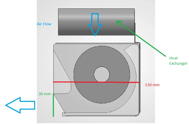
Here the system airflow diagram highlights the 130mm vertical heat exchanger clearance and the restrictive 30mm exit port.
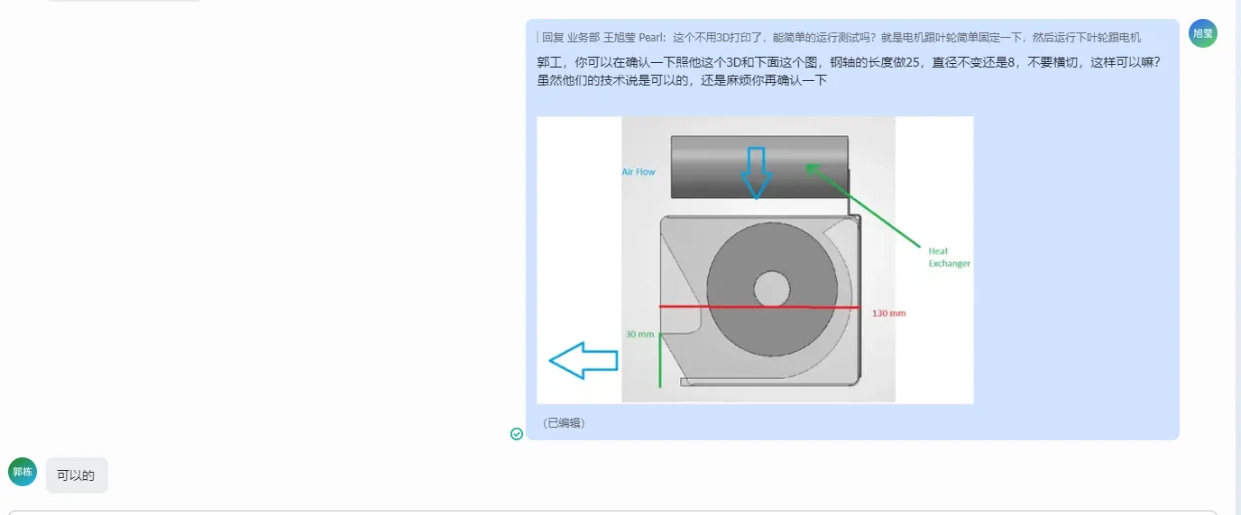
The technical PM chat confirms the required 25mm full-round shaft modification and the mandatory left-side chassis mounting.
Final impeller drawing, CW (PDF)
The final approved LWPI-φ90.5X615-08 specification sheet documenting the AS+GF30% material and CW rotation.
Initial motor specification (PDF)
The initial LWDM92M-011 motor drawing, which lacked the necessary CW optimization.
Final motor specification (PDF)
The final approved LWDM92M-013 technical document detailing the 24 VDC rating, CW rotation, and four-wire control pinout.
Specifying rotation properly
Fan rotation direction goes wrong quietly and late. Four habits keep it early and loud.
- State rotation with its viewpoint. Clockwise means nothing until you say from where. The convention is viewed from a named end, so write fan rotation direction as CW or CCW plus the reference face, and put it on the drawing, not in an email.
- Re-check rotation whenever the layout mirrors. Moving a motor to the other side of a chassis flips the required direction. Any late change that mirrors geometry should trigger a rotation review automatically, because CAD found this one and a bench build would not have.
- Never accept polarity reversal as a production fix. It works on the bench and erodes bearings, efficiency and acoustics in the field. If the direction is wrong, the motor variant is wrong, and the honest fix is the right variant.
- Treat the shaft interface as part of the rotation spec. Torque transmission, grip fit and balance all interact with direction. A coupling that relies on fit needs the tolerance stated, and a flat added for convenience can undo a balanced rotor.
See our cross-flow fans range, the DC cross-flow fans section, or cross-flow impellers.
Questions about rotation direction
Why does reversing polarity harm a DC fan motor?
Because the motor is built asymmetrically around its intended direction: bearing preload, magnetic timing and blade acoustics all assume it. Reversed, everything still turns, but each element runs off its design point, and the wear arrives over months rather than at switch-on.
How do I know which rotation my layout needs?
Trace the airflow path through the real chassis, then stand at the drawing reference face and see which fan rotation direction moves the air that way. Do it again after any mirror-image layout change, since rotation errors are almost always introduced by relocation, not by the first design.
Are cross-flow impellers direction-specific too?
Yes. The blade curvature is shaped to scoop air in one rotation only; turned backwards it moves far less air and makes more noise doing it. Impeller and motor have to agree on direction, which is why both were updated together here.
Why would a customer forbid a flat on the shaft?
A machined flat concentrates stress and disturbs balance on a long, slender rotor. A coupling that grips a plain cylinder avoids both, but it transfers the burden to the diameter tolerance, which is why the fit was specified to a hundredth of a millimetre.
Technical Documentation & Resources
Need the same thing for your own unit?
Give us the numbers and the envelope, and you get a shortlist rather than a catalog. Meanwhile custom spec sheets and samples run to 90 days. Since 1990 Longwell has supplied EC fans and blowers to OEMs in HVAC, cold chain, data center and industrial markets.
Browse Related Products:
🏆 ISO 9001 / ISO 14001 / ISO 45001 | CE (TÜV) | UL/ETL | ATEX Zone 21/22 | AMCA 210/211 / ISO 5801 tested
Choose the right cross flow fan
Longwell manufactures 487 cross flow fans in-house. Send airflow, static pressure and voltage — an engineer replies with a matching model, performance curve and price within one working day.