A fan schedule that says “300 CFM” but leaves the pressure cell blank is not ready for selection. The fan still has to move that airflow through straight duct, fittings, filters, coils, dampers, grilles, and the discharge. A useful duct static pressure calculation records those losses as a ledger instead of burying them in one unexplained allowance.
The worked figures below match the video and are illustrative. They show the arithmetic, not a universal duct design. Replace every friction rate, fitting coefficient, filter resistance, and component drop with current project or manufacturer data at the same airflow.
Set the boundary before adding pressure losses
Draw the air path and mark the two points between which pressure is being calculated. That boundary might run from the fan inlet to the fan outlet, or across the external components of a packaged unit. If a coil sits inside one definition but outside another, the same number cannot be used for both.
Name the pressure quantity as well. Static pressure is measured perpendicular to airflow at the duct wall; total pressure includes static and velocity pressure. The fan curve and the calculation must use compatible definitions. OSHA’s ventilation technical manual is a useful primary reference for these terms, pressure taps, manometers, and duct measurements.
Finally, lock one design airflow. Friction rate, velocity pressure, fitting losses, and component data all change with flow. If the project has normal, peak, clean-filter, and final-resistance cases, give each condition its own clearly labelled ledger.
Walk every branch and identify the critical path
Losses in series are added because the same air passes through each item. Parallel branches are different: calculate each complete path, then compare the totals. The highest-resistance route is the critical path that the fan must serve. Adding two parallel branch totals together is a common and expensive error.
A small path sketch beside the worksheet prevents ambiguity. Show shared duct, branch take-offs, terminals, and the selected inlet and outlet boundaries. If a damper is expected to balance an easier path, record its design position rather than quietly adding its loss to every branch.
Build a pressure-loss ledger that someone else can audit
Start with straight-duct friction. In the illustrative 300 CFM case, suppose the selected duct has a friction rate of 0.12 in. wg per 100 ft and the straight length is 60 ft. The entry is 0.12 × 60 ÷ 100 = 0.072 in. wg, rounded here to 0.07.
Next, account for fittings with one method. Using loss coefficients, fitting loss equals K multiplied by velocity pressure. An illustrative combined K of 2.0 and velocity pressure of 0.08 in. wg gives 0.16 in. wg. If a fitting table already expresses the loss as equivalent duct length, add that length to the friction calculation instead. Do not use both methods for the same fitting.
For filters, coils, grilles, dampers, silencers, and other components, use the supplier’s pressure-drop data at the target flow and stated condition. A defensible row includes the item, airflow, resistance, source document or curve revision, and any assumption. The U.S. Department of Energy’s fan-system sourcebook explains why duct geometry, leakage, system resistance, and installed conditions need to be treated as one system.
Calculate clean and loaded-filter duty points
The video’s example ledger uses 0.07 in. wg for straight duct, 0.16 for fittings, 0.10 for grille and damper, 0.20 for a clean filter, 0.25 for a coil, and 0.05 for discharge. The total is 0.83 in. wg, approximately 207 Pa. Again, those component values are teaching inputs, not Longwell product ratings or default design values.
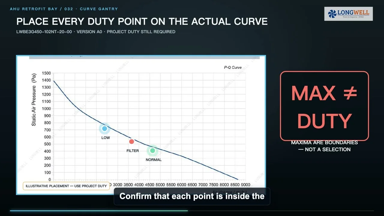
If the project’s specified final filter resistance is 0.40 rather than 0.20 in. wg, the same arithmetic produces 1.03 in. wg, approximately 257 Pa. The fan request should carry both tickets: 300 CFM at 0.83 in. wg for the clean case and 300 CFM at 1.03 in. wg for the loaded-filter case. The project must state which condition is required to maintain airflow and whether the motor and controls can support it.
Do not insert a generic safety factor simply because the installed layout is uncertain. Document the uncertainty, correct the geometry where practical, and use a project-specific allowance only when its basis is clear.
Keep leakage and system effect out of the arithmetic twice
Leakage changes how much air must move through upstream sections, so it belongs where the applicable leakage class or measured condition places it. System effect is different: poor inlet or outlet geometry can make installed fan performance depart from laboratory conditions. AMCA’s system-effect guidance describes turbulence, swirl, obstructions, and poorly arranged fan connections as common causes.
Do not count a documented elbow or transition loss and then hide the same effect inside “margin.” Improve the connection, obtain an appropriate system-effect allowance, or state the unresolved risk separately. That keeps the pressure ledger traceable and makes later troubleshooting possible.
Convert the ledger into an RFQ and verification plan
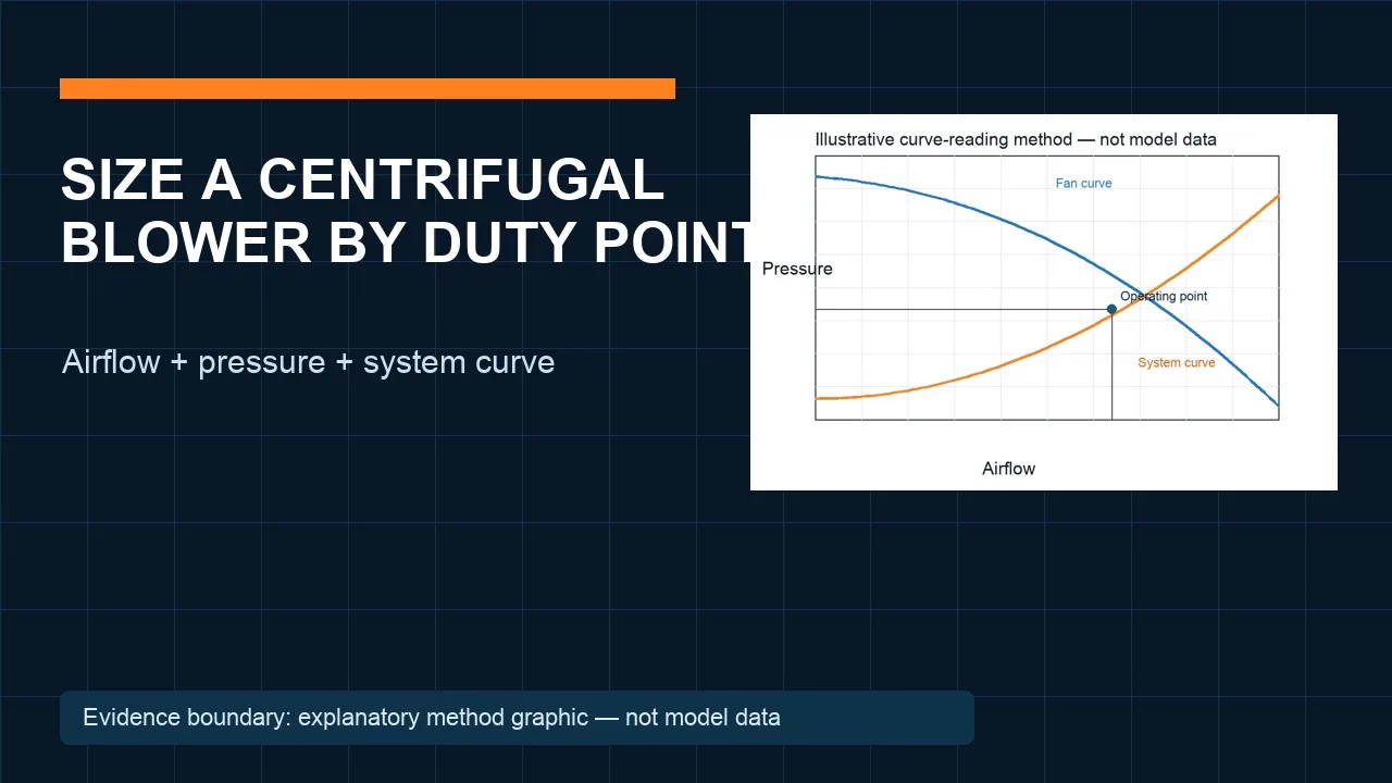
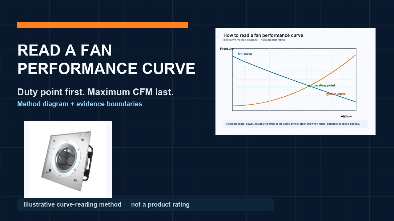
The handoff to a fan supplier should state airflow, pressure type, clean and loaded conditions, air density or elevation, voltage, speed or control signal, sound target, installation envelope, orientation, and discharge arrangement. Plot every required point on the exact current fan curve. Free-air CFM or duct diameter alone cannot prove installed performance.
Use Longwell’s mixed inline duct fan family only as an architecture-discovery route until the duty point and installation details are complete. The fan curve guide explains the next decision step, while the EC fan selection checklist helps organize electrical, control, sound, and envelope inputs. None of those pages substitutes for exact model data.
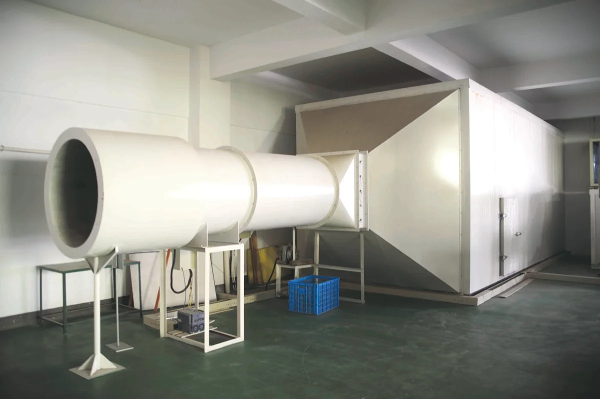
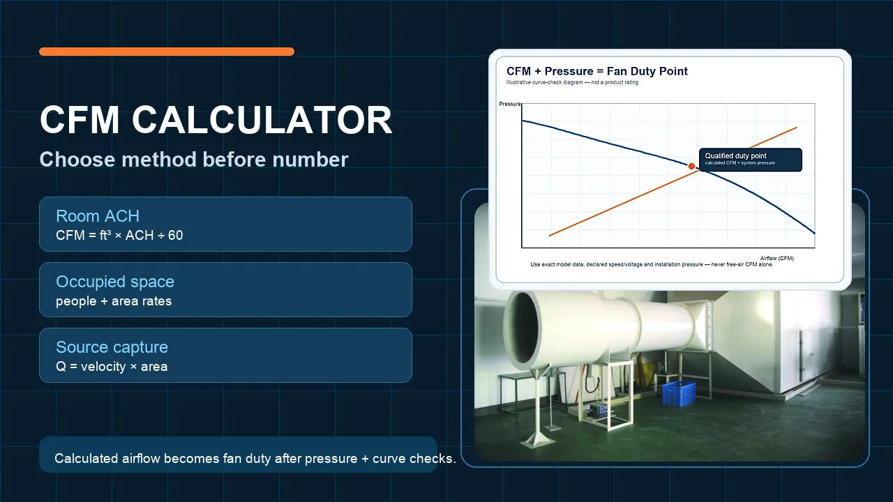
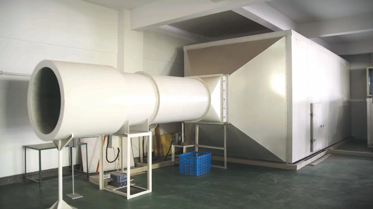
Plan the field check before fabrication. Provide suitable static-pressure taps in stable test sections and use an appropriate calibrated instrument. Record airflow, damper position, filter condition, fan command, and operating mode. The Longwell test-room photograph above shows visible measurement-duct structure only; it is not evidence of accreditation, a particular standard, or a product result.
If the installed readings differ from the ledger, look for an omitted component, a duplicated loss, leakage, a blocked path, or a disturbed fan connection. Do not alter the worksheet merely to force agreement. A completed pressure receipt should let a designer, contractor, buyer, and supplier reach the same duty point from the same evidence.
Choose the right duct fan
Longwell manufactures 254 duct fans in-house. Send airflow, static pressure and voltage — an engineer replies with a matching model, performance curve and price within one working day.