A hot-rod fan with a fail-safe clause
An OEM cooling high-density power electronics ordered a 120x120x38mm DC fan pushed far beyond catalog duty, and wrote locked rotor protection into the specification: a stalled rotor at rated voltage must not create fire risk for 72 hours.
Meanwhile the performance side was aggressive: 165.95 CFM from a 12038 frame on a 24 VDC bus, with the bus itself swinging between 12 and 26.5 V.
The rest of the envelope
- First, 19.8mm H2O static pressure at zero flow, tested to ISO 5801, because racks are dense.
- Next, 300 grams maximum, surviving 30cm drops onto wood on three faces.
- Meanwhile -10C to +60C and 5 to 90% humidity.
- Finally, UL Class A insulation, and UL1007 26AWG leads at exactly 300mm with specified pinouts.
Why the failure clause is the interesting one
Every other line assumes the fan works. By contrast, this line assumes it jams: a cable dropped into the blades, a bearing seizure, debris through an unguarded inlet.
A stalled motor stops converting electricity into motion, so everything it draws becomes heat in the winding. In short, the locked rotor protection clause decides what happens next.
How locked rotor protection works
Hitting the airflow meant driving the impeller to 5200 RPM, nearly double the base model. That made the locked rotor protection question sharper, not softer, because a hotter motor fails harder.
Two ways to protect a stalled motor
Firstly, a thermal cut-out is the active answer: a switch that opens when the winding overheats, added as a component.
Secondly, impedance protection is the passive answer, and it is what this fan uses for locked rotor protection. The winding itself is designed so that even stalled at full voltage, the current settles at a level the insulation absorbs indefinitely. No switch, no reset, nothing to fail.
Why 72 hours and not a spot check
A stalled fan in an unattended rack does not get found in minutes. Rather, it sits there, powered, over a weekend.
The 72-hour figure makes the test match that reality: three days at rated voltage with the rotor held, ending with no fire, no smoke, and insulation still intact. It converts stalls safely from a claim into a demonstrated property.
The tension with the hot-rod duty
Locked rotor protection by impedance is easiest on a lazy winding and hardest on one already pushed to 18 W continuous. After all, the stall current and the performance current come from the same copper.
Consequently the winding design carried both requirements at once, and the drop test added a third: whatever survives the stall heat must also survive three 30cm impacts undegraded. The 300-gram cap ruled out solving anything with mass.
What shipped
Finally, a 5200 RPM build on dual ball bearings for the 50,000-hour life, holding the pressure figure to ISO 5801, with the stall behavior demonstrated rather than asserted.
Technical Specifications
One line below describes the fan failing: the locked rotor clause. It is the line the safety file cares about most.
| Parameter | Specification |
|---|---|
| Rated Voltage | 24.0 VDC |
| Operation Voltage | 12 – 26.5 VDC |
| Input Current | 0.75 A (Max 1.0 A) |
| Input Power | 18 W (Max 24 W) |
| Speed | 5200 RPM (±10%) |
| Maximum Air Flow | 165.95 CFM (Min. 149.35 CFM) |
| Maximum Air Pressure | 19.8 mm H2O (Min. 17.82 mm H2O) |
| Insulation Type | UL: CLASS A |
| Insulation Strength | 10 Meg OHM MIN. At 500VDC |
| Dielectric Strength | 5 mA Max, at 500VAC~80Hz, 1 Minute |
| Dimensions | 120 ± 0.5 x 120 ± 0.5 x 38 ± 0.5 mm |
| Weight | 300 Grams |
| Operating Temperature | -10 °C ~ +60 °C |
| Life Expectancy | 50,000 Hours at 25°C (15~65% RH) |
Technical Documentation
Here the original specification sheet detailing the electrical parameters and mechanical drop testing requirements can be viewed here: LWAD12038MX-29-00 Word Specification. Procurement teams require this document to verify wire lengths and pinout configurations before integrating the fan into their assembly line.

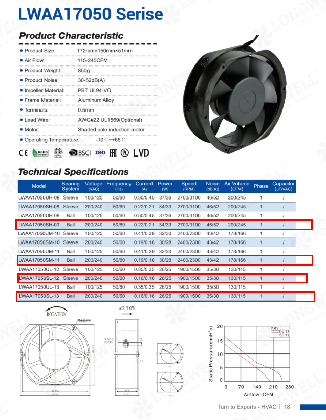
The catalog excerpt shows the standard series baseline, highlighting the jump in performance required for this specific custom build.
For engineering sign-off, the finalized P-Q curve and dimensional drawings are available in the approved PDF release: LWAD12038MX-29-00 PDF Engineering Drawing. HVAC and thermal engineers will use the P-Q curve on page 4 to map the fan’s performance against their specific system impedance.
Specifying for the failure case
Specifying for failure is what separates a safety file from a datasheet. Four habits carry it.
- Write the stall clause with a duration. Locked rotor protection claimed without a time bound means a five-minute bench check. Stating 72 hours makes the test match an unattended weekend, which is the failure that actually happens.
- Know which protection type you are buying. Impedance protection needs no reset and never wears out; a thermal cut-out reacts faster but adds a component and sometimes auto-restarts a jammed fan. Which is safer depends on your product, so choose rather than inherit.
- Re-verify protection after any performance push. A winding modified for more speed carries different stall behavior than the catalog version. The safety property does not transfer automatically with the model number.
- Confirm the insulation class against stall temperature, not running temperature. The winding is hottest precisely when the fan has failed. Class A was sufficient here because the impedance design caps the stall heat; that pairing is the design, not a coincidence.
See our axial fans range, the DC axial fans section, or DC cooling fans.
Questions about locked rotor safety
What does impedance protected actually mean?
It means the motor winding is designed so a stalled rotor at rated voltage draws only a current the insulation can absorb indefinitely. The protection is a property of the winding itself, with no switch or sensor involved, which is why it cannot wear out or fail to reset.
Is a fuse not enough to protect a stalled fan?
A fuse protects against overcurrent, and a stalled fan may not draw enough to blow one, especially an impedance-limited design. The hazard is sustained heat rather than a current spike, which is why the requirement is framed in hours at temperature, not amps.
Why would a fan stall in the field at all?
Cable intrusion, debris through an unguarded inlet, bearing seizure at end of life, or ice on a cold start. Unattended equipment makes it worse, since nobody clears the jam. The design assumption should be that a stall will eventually happen somewhere in the fleet.
Does the 72-hour test damage the fan?
It ages the winding, but the fan is not expected to serve afterwards; the requirement is failing safely, not surviving. The demonstration consumes the stall test units, which is one more reason to prove the property on samples rather than production units.
Technical Documentation & Resources
Need the same thing for your own unit?
Give us the numbers and the envelope, and you get a shortlist rather than a catalog. Meanwhile custom spec sheets and samples run to 90 days. Since 1990 Longwell has supplied EC fans and blowers to OEMs in HVAC, cold chain, data center and industrial markets.
Browse Related Products:
🏆 ISO 9001 / ISO 14001 / ISO 45001 | CE (TÜV) | UL/ETL | ATEX Zone 21/22 | AMCA 210/211 / ISO 5801 tested
Choose the right axial fan
Longwell manufactures 1,067 axial fans in-house. Send airflow, static pressure and voltage — an engineer replies with a matching model, performance curve and price within one working day.