A vibrating fan does not automatically need a balance weight. The useful first decision is whether the rotor has a repeatable unbalance response, or whether dirt, damage, loose mounting, bearing condition or airflow is producing the vibration. Once that question is answered, balancing becomes a measured correction loop: establish a baseline, use a controlled trial mass, calculate the correction and verify the remaining unbalance.
First decide whether unbalance is the fault
Unbalance can produce a once-per-revolution vibration component, but a 1× component by itself does not prove the cause. Inspect the wheel for uneven deposits, missing material, loose parts and rubbing. Check the bearings, shaft fit, mounting and nearby structure. Compare readings at repeatable speed and sensor positions, including phase where the procedure calls for it. A changing signature or a new noise may point to another fault; a balancing run would then hide the symptom rather than remove the cause.
Cleaning should be documented before a baseline is accepted. A deposit can move or detach after a correction weight is fitted, changing the rotor again. The related fan-vibration diagnosis guide helps separate possible causes, while the measurement plan for a specific machine must come from the responsible engineer and applicable procedure.
Set the safety and configuration boundary
A rotating impeller and any trial or correction mass can eject material. Balancing belongs in a rated machine or approved in-situ setup with the required guards, interlocks and exclusion zone. Stop the rotor, confirm zero speed and isolate against unintended startup before touching it or changing a weight. The exact machine limits, fastening method and acceptance criterion are project-specific; this article is an explanation of the decision sequence, not an operating instruction for unguarded balancing.
Freeze the assembly that will be evaluated: wheel, hub, shaft or adapter, fasteners, direction, speed range and correction planes. Record where the phase reference and vibration sensor are mounted. If a component or fixture changes between runs, the before-and-after vectors may no longer describe the same rotor system.
Use the baseline, trial and verification loop
At a stable agreed speed, record the baseline 1× amplitude and phase. Stop safely, attach a known trial mass at a documented radius, angular position and plane, then repeat the measurement under the same conditions. The change in the measured vector shows how that rotor and setup respond to mass in that plane. Calculate the proposed correction from the measured response, fit it by an approved method, then run again to measure residual unbalance. An unexplained or nonrepeatable vector is a reason to stop and diagnose, not to guess a larger weight.
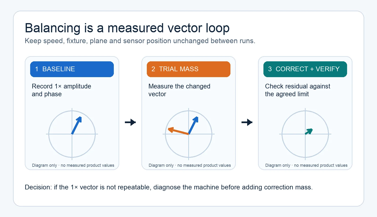
The video shows the sequence visually. Use it to understand what the measurements mean; a particular machine’s approved procedure and the rotor’s agreed requirement still determine the actual masses, speed and acceptance decision.
What a balancing-station photograph can and cannot show
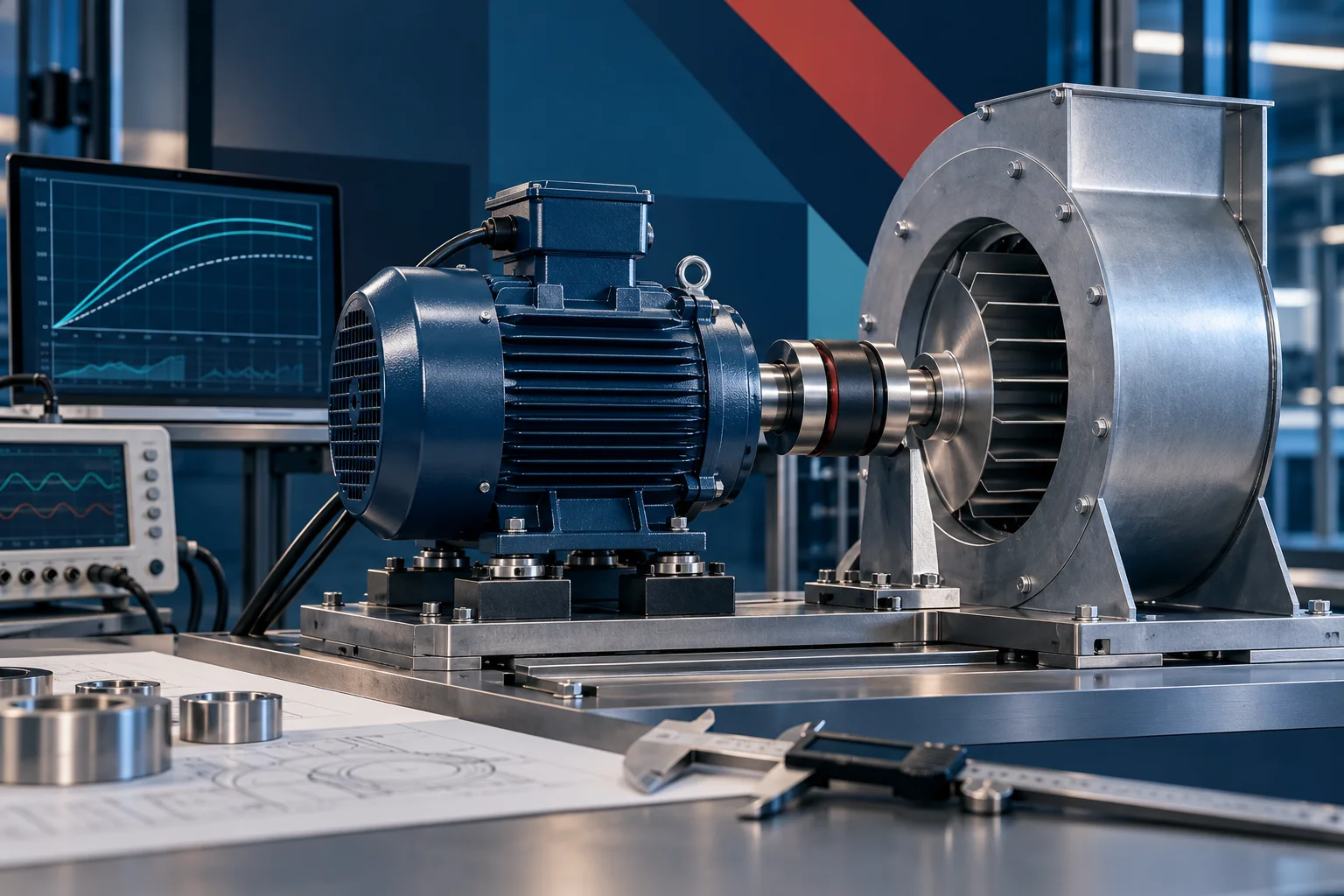
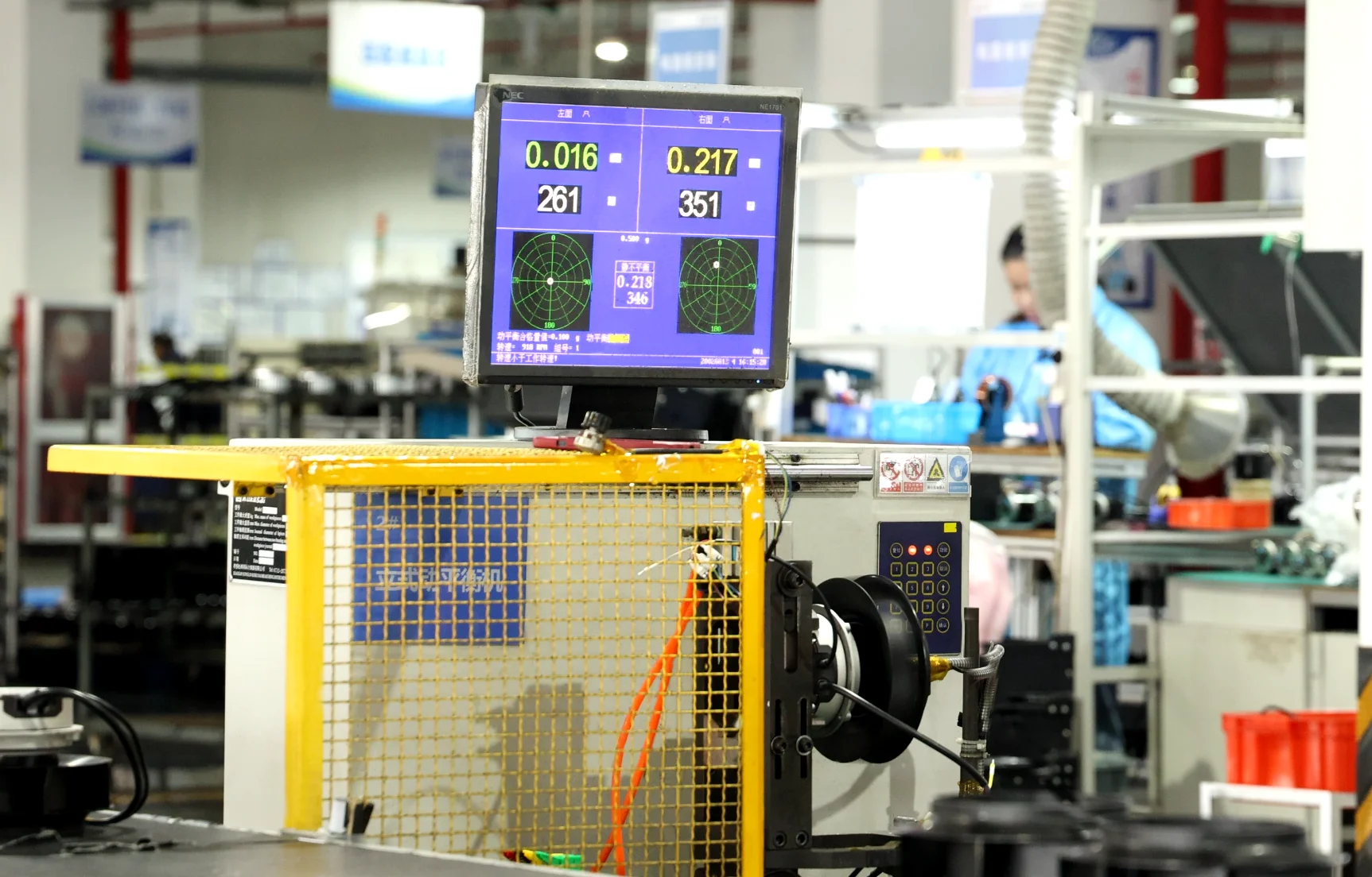
The LONGWELL workshop photograph below shows a guarded balancing station and its display. It is useful for identifying the physical measurement environment. Its screen belongs to the photographed session: the visible numbers are not a published acceptance record for the rotor in this article and must not be copied into a specification. For an actual order, ask for the exact model suffix, drawing revision, balance requirement and traceable test record.
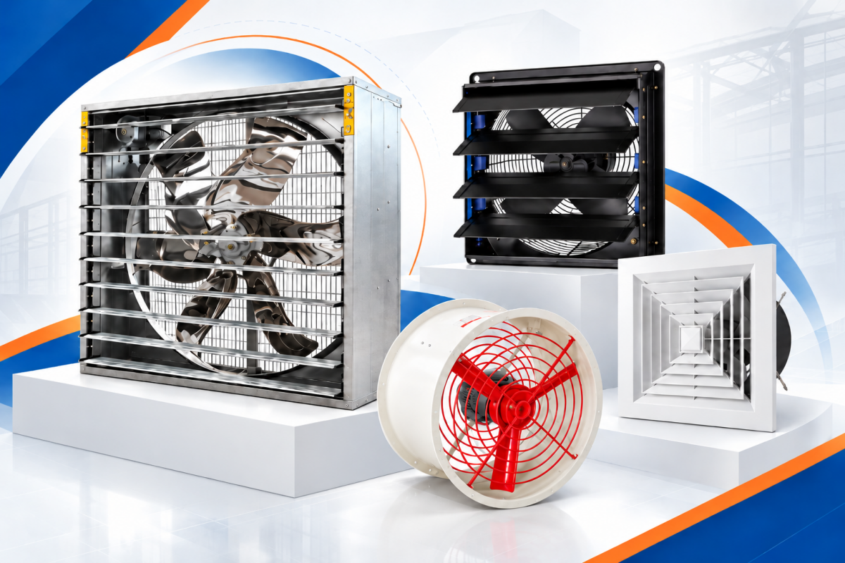
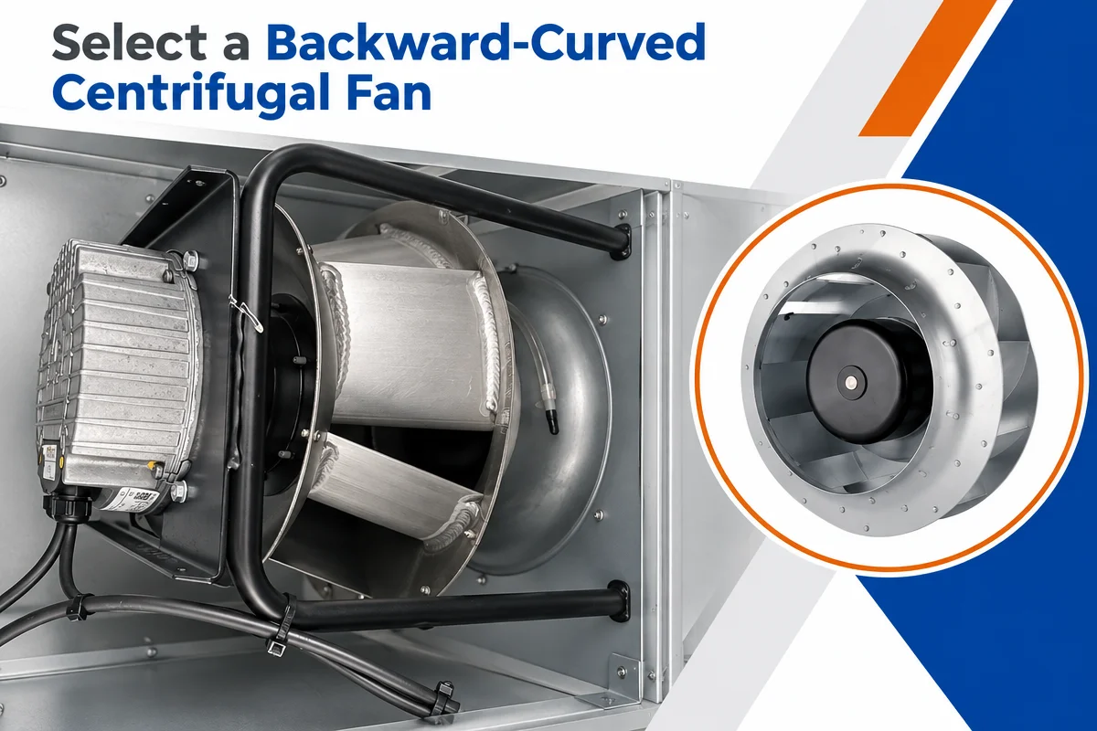
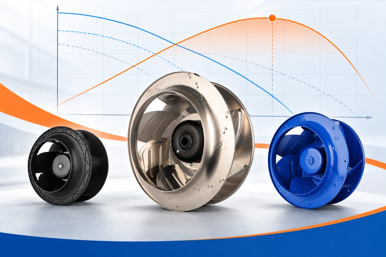
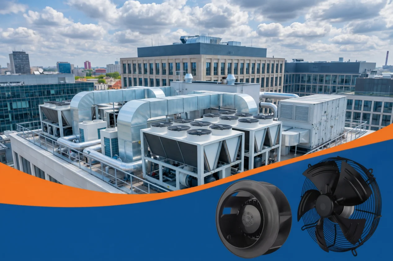
The LONGWELL centrifugal-fan family shows the available construction categories. A family page can identify candidates, but it cannot establish a balancing result or suitability for a particular installation. The exact model document and inspected test record are needed for those claims.
Choose the planes and acceptance criterion for the actual rotor
A narrow rotor that behaves rigidly may be handled differently from a long assembly with a significant couple response. The required number of correction planes cannot be decided from the wheel photograph alone. ISO 21940-11 describes procedures and unbalance tolerances for rotors with rigid behaviour, including the number of correction planes and allocation of permissible residual unbalance. It does not replace a project specification or cover every flexible rotor.
Likewise, rotor residual unbalance and vibration of the installed fan are separate checks. ISO 14694 addresses balance quality and vibration levels for industrial fans within its scope. Do not quote a universal G grade or a single mm/s limit for all fan types, mounting arrangements and service conditions. Record the specified category, measurement method and acceptance basis before reporting a pass.
Fit the correction securely, then verify and record
The correction method has to suit the wheel material, speed, temperature and approved design. A weight must remain attached throughout the permitted operating range without interfering with the flow path or nearby parts. Welding, bolting, material removal or another method may be appropriate only when the manufacturer and procedure allow it. Do not grind a blade or attach an improvised weight simply because the calculated vector points there.
After the final run, save the configuration, measurement conditions, baseline, trial mass, calculated correction, final residual and acceptance reference together. Recheck an assembled or installed fan under its defined conditions if the project requires it; a rotor balance result alone does not eliminate structural resonance, aerodynamic excitation or installation faults. The separate unbalanced-wheel diagnosis guide explains symptoms to investigate when vibration returns.
What to send for an engineering review
Provide the rotor drawing and exact suffix, wheel and assembly mass, operating and balancing speeds, mounting/fixture details, available correction planes and radii, the recorded 1× amplitude and phase, and the required balance or installed-vibration criterion. State whether the wheel has been cleaned and inspected and whether any component has changed since the last test. Those inputs support a specific plan; an article, a photograph or a generic family listing cannot substitute for them.
Choose the right fan impeller
Longwell manufactures 10 fan impellers in-house. Send airflow, static pressure and voltage — an engineer replies with a matching model, performance curve and price within one working day.