Fan vibration is a symptom, not a diagnosis. A strong peak at running speed may be consistent with rotor unbalance, but the same fan also has a wheel, bearings, drive, frame and air system that can change the measured response. The practical decision is which observation to collect next before ordering a balancing job or replacement part.
This guide groups six useful checks into rotor, mechanical and airflow paths. It does not assign a cause from one sound or one spectrum peak. Stop and follow the equipment maker’s isolation procedure before touching the fan, and have qualified personnel measure a running machine.
Start with a repeatable baseline
Record the exact fan and installation, operating speed, drive arrangement, measurement location and direction, load or damper position, and whether the vibration is steady or changes during a run. Compare like with like: a bearing-housing reading at one speed cannot be treated as the same observation as a frame reading at another speed. A trend is useful only when the sensor position and operating condition are documented.
If there is rubbing, a visibly loose part, damaged guard or severe new motion, isolate the equipment and inspect it before another test run. Otherwise, compare overall level, spectrum and phase with the equipment’s own history and the acceptance criteria agreed for that specific machine. SKF’s spectrum-analysis guide explains why spectra and phase are diagnostic inputs rather than fault labels.
Read patterns as clues, then inspect the machine
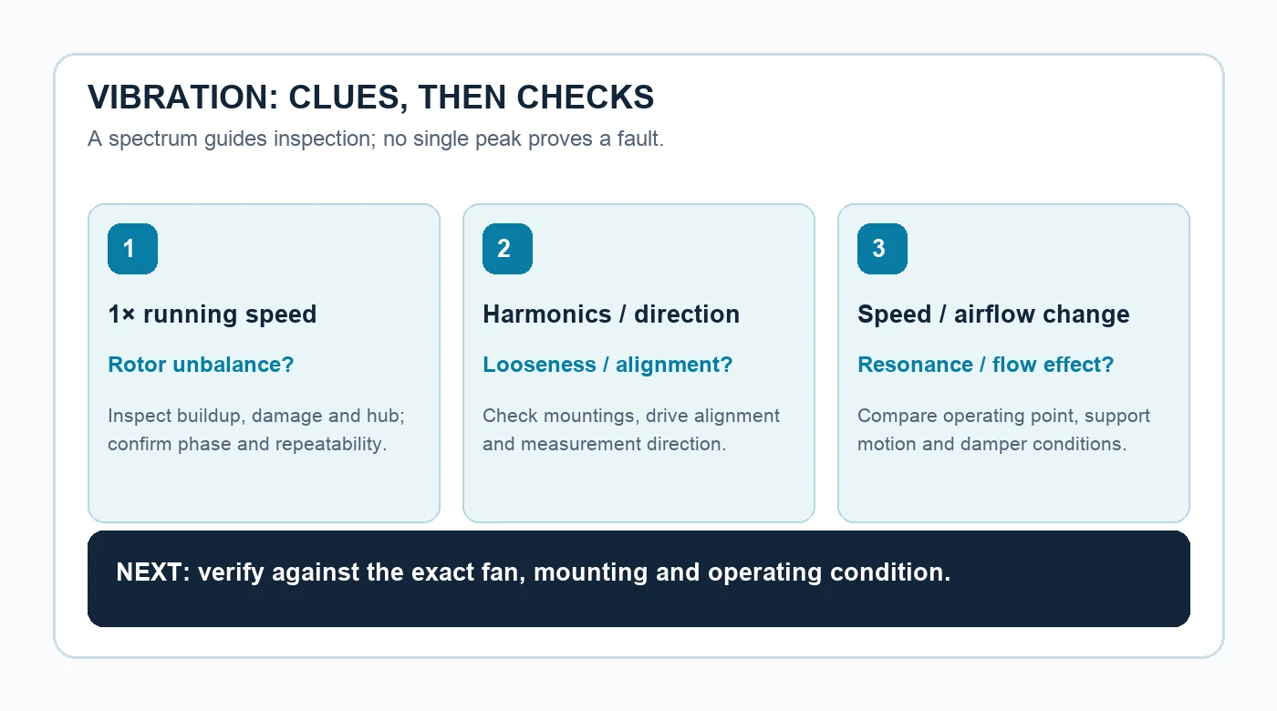
A prominent once-per-revolution component can suggest unbalance, but it can coexist with other faults. Harmonics and direction can steer attention toward looseness or drive alignment. A response that changes sharply with speed or damper position points the investigation toward the support structure or air path. The diagram is an inspection map, not a table that converts one frequency into a certain failure.
1. Check the wheel for buildup, damage and unbalance
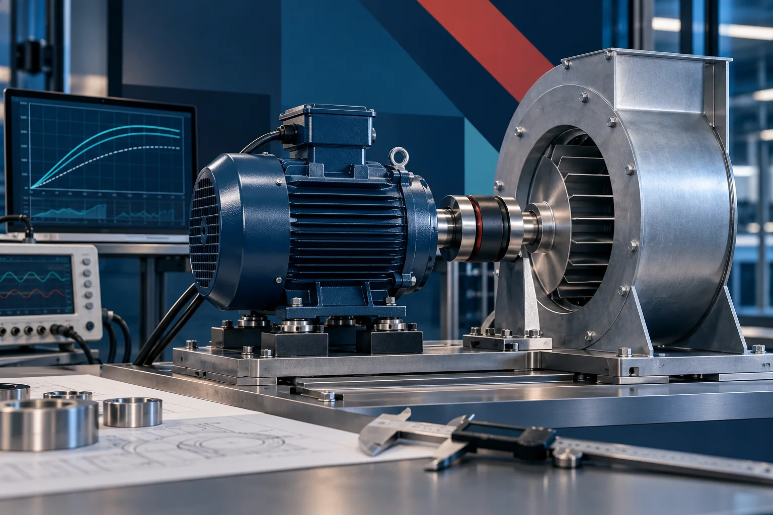
Uneven deposits, missing material, a damaged blade or a changed hub fit can move the rotor’s mass distribution. With the equipment safely isolated, compare the wheel with its approved condition and look for buildup or mechanical damage. If the installation and inspection point to unbalance, a balancing specialist can use amplitude and phase to plan and verify correction. The LONGWELL impeller-balancing guide describes that workflow; its examples are not acceptance values for this fan.
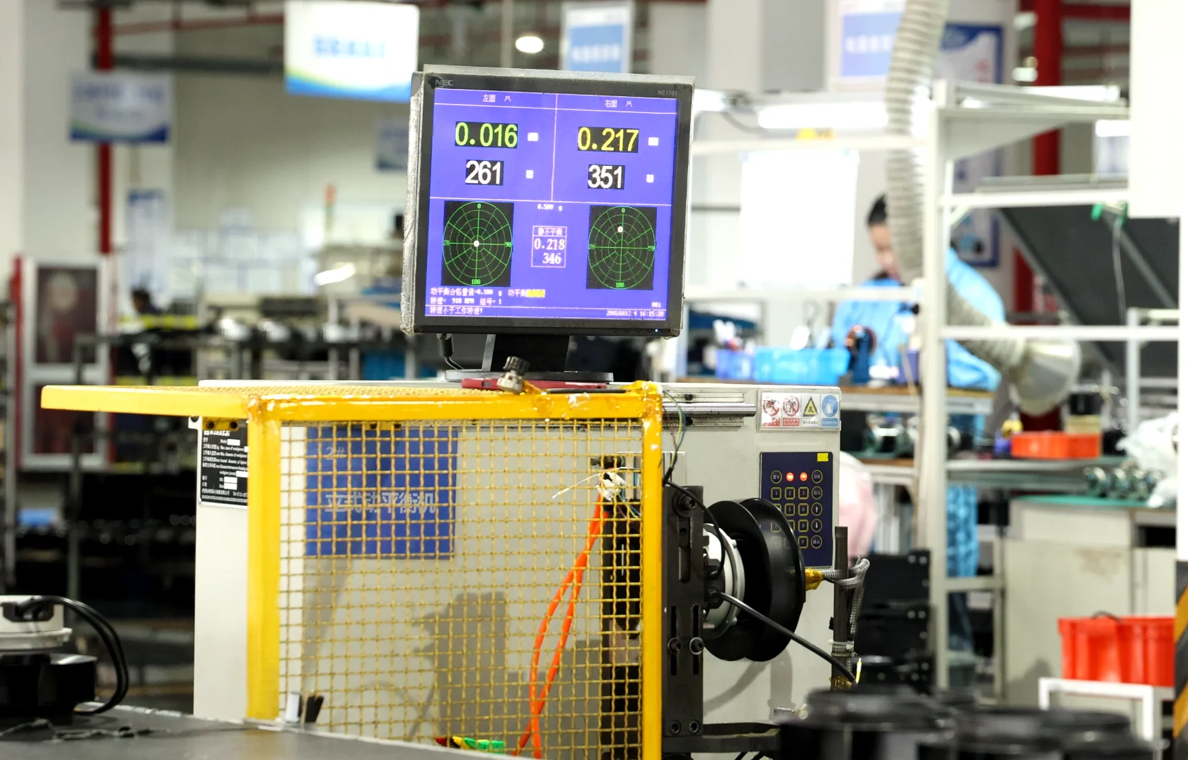
The photograph shows a guarded LONGWELL balancing station. It establishes that such equipment is part of the company’s production setting, not that the article’s fan was measured there or that the numbers visible on its display are universal limits. For an impeller selection or replacement review, the LONGWELL fan-impeller family is a product-family starting point. Match the exact drawing, hub, direction, speed and application before treating any listed wheel as a fit.
2. Inspect drive alignment and 3. Verify mountings
On a belt or coupled drive, pulley or coupling alignment and belt condition deserve a separate inspection. Check them against the drive manufacturer’s method instead of reading a single spectral harmonic as proof of misalignment. Loose fasteners, soft foot, cracked supports and contact between rotating and stationary parts can also produce motion or harmonics. Record what is loose before tightening; otherwise a useful symptom may disappear without identifying the source.
After correcting an identified mechanical issue, repeat the measurement at the same operating point. If the machine vibration is acceptable but the building or duct shakes, investigate the transmission path as a separate decision. The LONGWELL mounting and isolation guide explains that distinction; an isolator does not repair a bad bearing or damaged wheel.
4. Test bearing condition and 5. Check for resonance
Bearing condition needs a combination of history, listening, temperature where appropriate, lubrication records and suitable vibration measurements. A high-frequency feature alone is not a replacement instruction: sensor position, other machine components and the bearing type matter. Isolate and inspect any suspected bearing fault under the equipment procedure, then compare it with the part and service record.
Resonance is a different question. If vibration rises strongly in a narrow speed band and falls outside it, compare the fan, base and duct responses over the approved operating range. Do not sweep through an unsafe speed or assume a speed change is permissible. A structural specialist may need to evaluate the support. Balancing a wheel cannot remove a support resonance by itself, although multiple causes can occur together.
6. Compare the air path and operating point
Inlet obstruction, disturbed inflow, a changed damper setting or operation away from the intended fan duty can alter aerodynamic forces. Compare the vibration while documenting airflow controls and system conditions; do not move a damper solely to make a vibration reading look better. Inspect the inlet, outlet and connected ductwork against the fan’s installation drawing. A changed airflow condition is a clue to test, not automatic proof of stall or a defective impeller.
Set the decision and evidence boundary
There is no single vibration velocity in this article that declares every fan good or bad. An acceptance decision needs the applicable standard edition or contract, fan category, mounting, measurement position, operating state and baseline. Keep the raw trace and inspection notes with any recommendation. If a part is to be replaced, check its exact model and revision, rather than matching a photograph or a family name.
For a useful engineering review, send the fan nameplate and drawing, speed and control mode, bearing and drive details, measurement locations and directions, spectra or time trends, photos of the wheel and mounting, and the observed damper or load condition. That package lets an engineer choose the next inspection and distinguish a rotor issue from a support or air-system issue without promising an answer that the current evidence cannot support.